System Description
4-2 Opus Operator's Manual
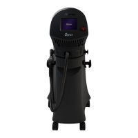
4.2.1 System Controls
The control system incorporates the following features:
• Emergency shutoff knob: this is a red, mushroom-like knob designed for
emergency shutdown of the system.
• Keyswitch: this turns on the Main User menu after the system is activated.
• Touch-screen LCD display: the LCD display provides information on the
status and settings of the system, with touch-screen technology for system
operation.
4.2.2 Service Panel
The service panel is located at the bottom of the system's rear panel. It incorporates
all the required controls and connections for the system:
• Main power cable connection port.
• Housing for two surge-protection fuses.
• Main switch (green) used to activate the micro-processor and the LCD
display.
• Footswitch connection port.
• Electrical current indicator; it illuminates when the power cable is
connected to the wall outlet.
All of the service panel's components are described in detail in Controls and
Indicators chapter.
4.2.3 System Software
The system is a computerized system with embedded software that controls its
operation.
The software controls the operating parameters, runs routine tests to ensure proper
and safe operation, and coordinates its various sub-systems.
The software also runs the graphical user interface, which enables user-friendly
4.2.4 Fans
Several fans are located inside the system.