Opus Operator's Manual 5-1
Controls and Indicators
5.1 Introduction
This chapter describes in detail the system controls, indicators and connections.
They include:
• Control panel components
• Service panel components
• Applicator connection port
• Emission control systems
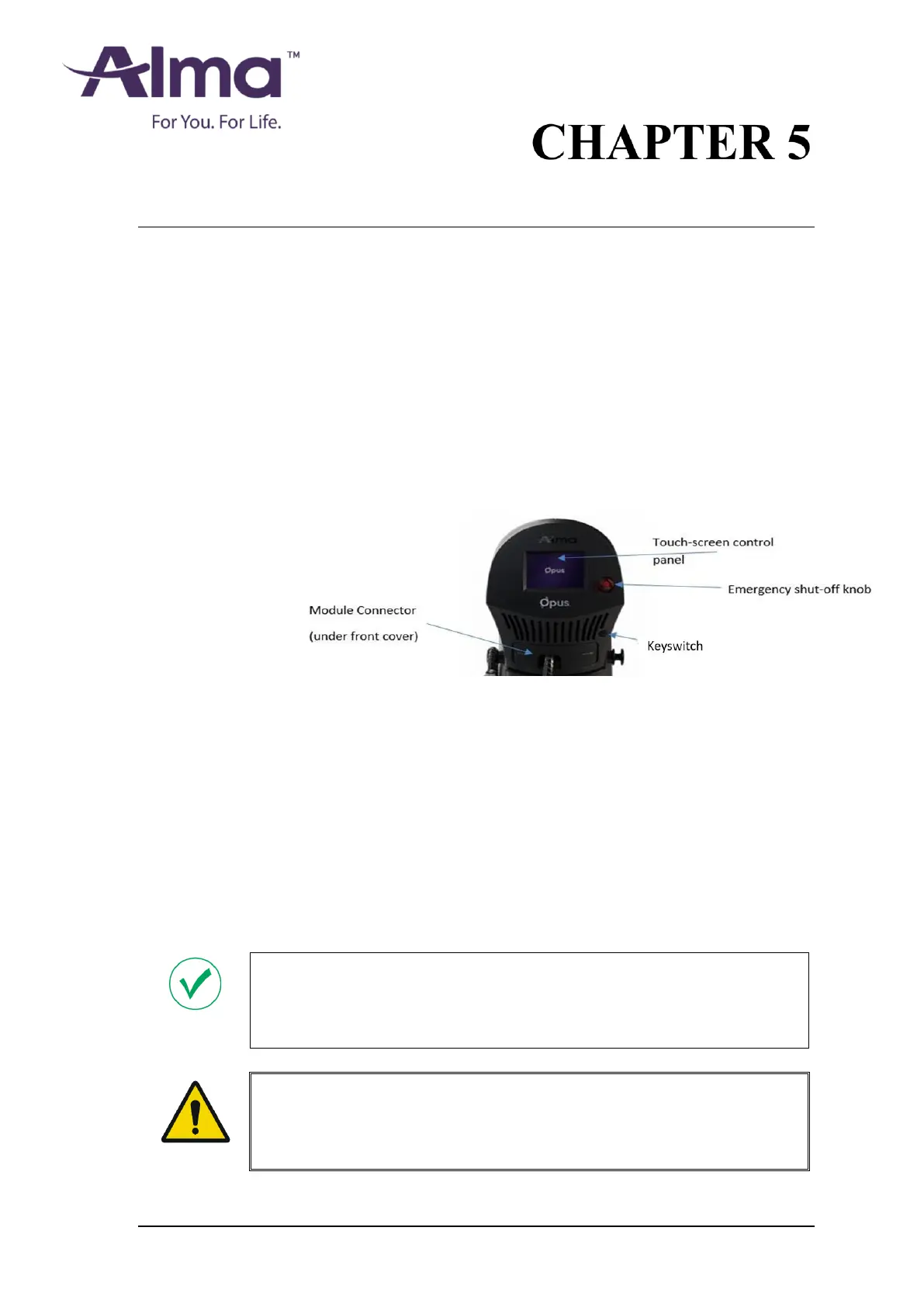
5.2 Control Panel Components
The control panel is located on the system's front side, as shown in Figure 5-1:
Figure 5-1. System Control Panel
5.2.1 Key switch
The key switch is located at the center of the control panel (see above Figure 5-1),
and is used to turn the system on and off:
• Turning the key switch clockwise turns the system on.
• Turning the key switch counterclockwise starts the shut-down sequence and
turns off the system.
Once the keyswitch is turned to the OFF position the key should be removed to
prevent unauthorized use of the system. The key cannot be removed when the
keyswitch is in the ON position.
Note
In an emergency situation, press the emergency shut-off knob to shut down the
system immediately (see section 5.2.2).
Warning
To avoid misuse of the system, do not leave the key in the key switch while the
system is unattended.