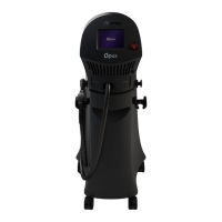
Controls and Indicators
5-2 Opus Operator's Manual
5.2.2 Emergency Shut-Off Knob
The emergency shut-off knob is located at the right of the control panel (see Figure
5-1 above).
In case of an emergency, pressing the emergency shut-off knob shuts down the
immediately by cutting off the electrical supply to the system.
To resume system operation, turn the emergency shut-off knob clockwise, to
release it (the knob pops out); then restart the system.
Caution
Use the emergency shut-off knob only in case of an emergency.
5.2.3 Touch-Screen Panel
The transparent touch-screen panel overlays the LCD graphic display.
The touch-screen panel provides the primary means of communication between the
operator and the system.
The computer-controlled graphic user interface keeps the operator informed of the
system status and operating parameters at all times.
The operator controls the system, using the touch-sensitive softkeys and indicators
that appear on the LCD.
For a detailed description of the graphic user interface, refer to Chapter 6 –
Operating Instructions.
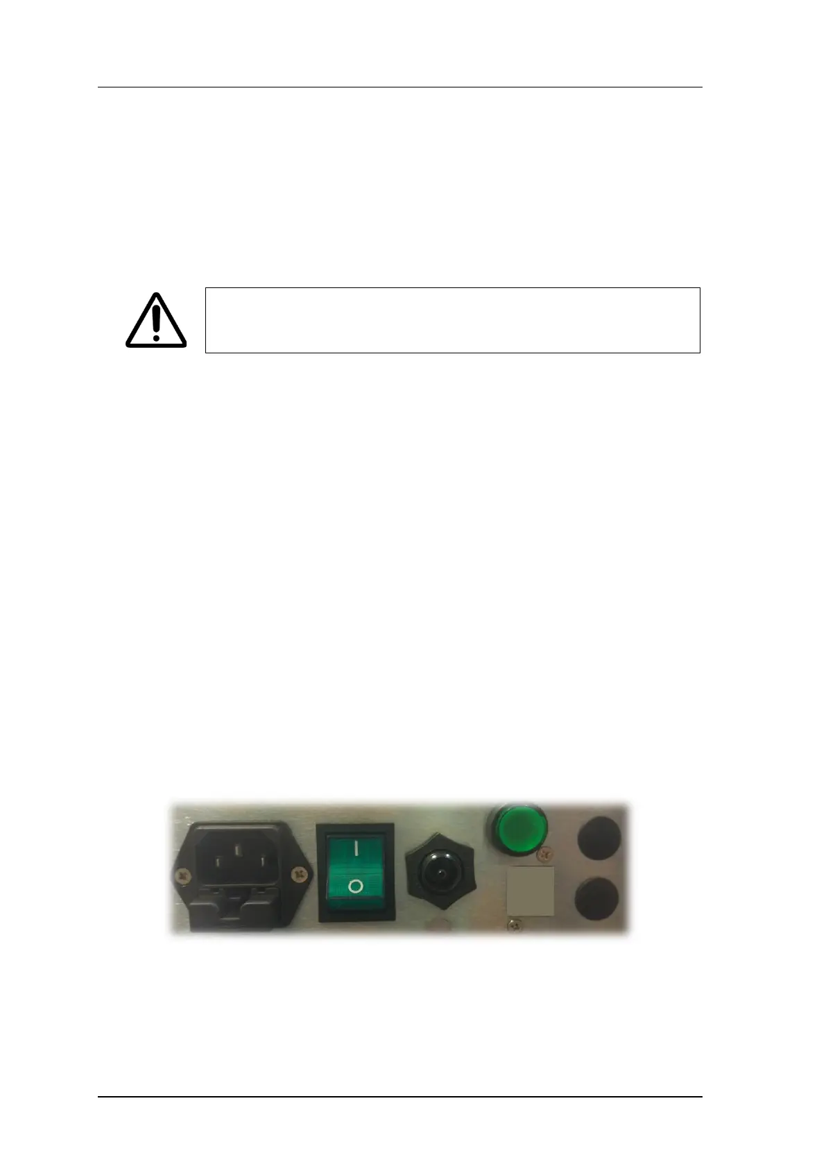
5.3 Service Panel Components
The service panel (see Figure 5-2) incorporates the following system controls and
connections:
• Footswitch air tube connection port
• Power cable connection port (appliance coupler)
Figure 5-2. Service Panel Components
5.4 Footswitch
The pneumatic footswitch (see Figure 5-3), supplied with the system activates the
radiofrequency emission.