List of Figures
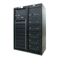
Figure 1 — CXPS-C Centralized Power Plant Basic System ........................................................... 8
Figure 2 — Basic Power System .................................................................................................... 12
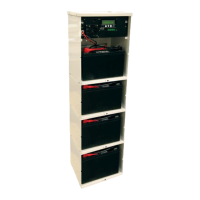
Figure 3 — Stand-alone Power Bay showing DC Charge Buses ................................................... 14
Figure 4 — Top View of Horizontal Inter-bay Busbars .................................................................... 14
Figure 5 — 4.0kW Rectier Front Panel LEDs ............................................................................... 15
Figure 6 — 12kW (3-phase) Rectier Front Panel LEDs ................................................................ 15
Figure 7 — Distribution Panel Options ............................................................................................ 17
Figure 8 — 4 Position TPL .............................................................................................................. 18
Figure 9 — 12x 1 Position High Capacity Breaker .......................................................................... 18
Figure 10 — 6x 2 Position High Capacity Breaker .......................................................................... 19
Figure 11 — 4x 3 Position High Capacity Breaker .......................................................................... 19
Figure 12 — 3x 4 Position High Capacity Breaker .......................................................................... 20
Figure 13 — 2x 5 Position High Capacity Breaker .......................................................................... 20
Figure 14 — 2x 6 Position High Capacity Breaker .......................................................................... 21
Figure 15 — 4x2 & 4x1 Position High Capacity Breaker ................................................................ 21
Figure 16 — 18 Position Bullet Breaker .......................................................................................... 22
Figure 17 — 18 Position Bullet Breaker Return .............................................................................. 22
Figure 18 — Distribution Bay—DC Distribution Bus ....................................................................... 23
Figure 19 — Distribution Shunts ..................................................................................................... 24
Figure 20 — Inter-bay DC Connections .......................................................................................... 25
Figure 21 — External Battery Return Ground Bar .......................................................................... 26
Figure 22 — Cordex CXC HP Controller ........................................................................................ 27
Figure 23 — LCD Color Touchscreen Display ................................................................................ 27
Figure 24 — L-ADIO I/O Peripheral ................................................................................................ 28
Figure 25 — 6I-ADIO Peripheral ..................................................................................................... 29
Figure 26 — Redundant Input Power Module ................................................................................. 30
Figure 27 — Shelf/Bay ID ............................................................................................................... 30
Figure 28 — Base Dimensions and Mounting Holes ...................................................................... 34
Figure 29 — Securing Power System to Concrete Floor ................................................................ 35