59400001-J1 Rev F
Figure 30 — Bolting Adjacent Bays Together ................................................................................. 36
Figure 31 — Example of Installed Inter-bay Buswork ..................................................................... 38
Figure 32 — Shunt Connections ..................................................................................................... 39
Figure 33 — Inter-bay Wiring Harness ........................................................................................... 39
Figure 34 — CAN OUT Port Terminator .......................................................................................... 40
Figure 35 — Controller, CAN Bus cabling 4.0kW Power Bay ......................................................... 40
Figure 36 — Controller and Shelf/Bay ID, CAN Bus and Shelf ID cabling ...................................... 41
Figure 37 — CAN Bus Termination 4.0kW ...................................................................................... 42
Figure 38 — CAN IN/CAN OUT Connection 4.0kW ....................................................................... 42
Figure 39 — Battery Disconnect Connections ................................................................................ 43
Figure 40 — External Battery Return Bar Kit .................................................................................. 44
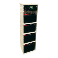
Figure 41 — Battery Installation ...................................................................................................... 45
Figure 42 — Battery Temperature Probes ...................................................................................... 46
Figure 43 — Battery Return Busbars, Frame Ground and Battery Return Reference .................... 50
Figure 44 — AC Distribution ........................................................................................................... 51
Figure 45 — Pre Wired 8-feed AC Panel - 3 Phase, 3 Wire 208/480 Vac ...................................... 52
Figure 46 — Terminal Blocks for 8-feed 3 wire 208/480Vac input .................................................. 53
Figure 47 — Terminal Blocks for 16-feed 208/480Vac input ........................................................... 53
Figure 48 — Terminal Blocks for 6-feed 480Vac input .................................................................... 53
Figure 49 — High Capacity Breaker Panel Alarm Wiring ................................................................ 54
Figure 50 — External Battery Return Bar Wiring ............................................................................ 55
Figure 51 — Customer Connections Spacing ................................................................................. 56
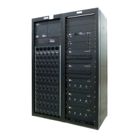
Figure 52 — Example of a Single Bay with Two Rectier Shelves. ................................................ 60