hypercharger - Operation Instructions and Installation Guide
Hardware
Version 2-2
All rights reserved. The reproduction of this document, also partially, is allowed only with authorization by alpitronic Srl
2.4. Internal view
2.4.1. HYC_150 internal view
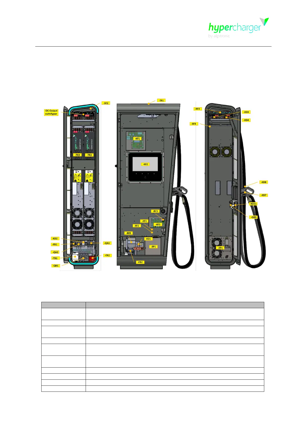
The following figure shows the hypercharger internal view of HYC_150.
Figure 13: Internal view hypercharger HYC_150 (service-, display-, charging cable side)
The following table describes the single components indicated in the figure above:
DC fault current monitoring for AC charging (optional, only when AC-socket
or AC cable is present)
Cooling unit for cooled charging cable (optional, only with cooled charging
cable)
Lightning protection and EMI filter device
10 A circuit breaker with fault current monitoring for internal supply and
service-socket
32 A circuit breaker with fault current monitoring (optional, only with AC-
Socket)
CTRL_COM_HD control board, CTRL_COM Display
125 A circuit breaker / 3P
 Loading...