VCU118 Board User Guide 18
UG1224 (v1.5) March 15, 2023
Chapter2: Board Setup and Configuration
For complete details on configuring the FPGA, see UltraScale Architecture Configuration
User Guide (UG570) [Ref 2].
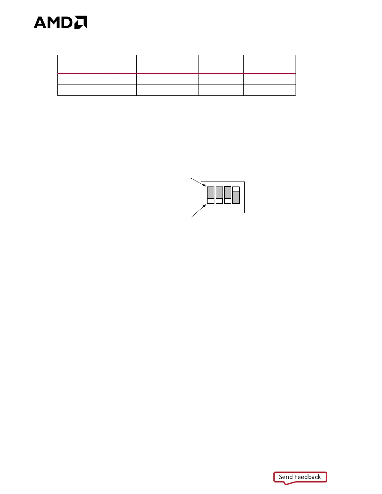
Figure 2-4 shows the configuration mode DIP switch SW16 JTAG switch positions.
See the VCU118 Software Install and Board Setup Tutorial (XTP449) [Ref 15] for more
information.
See System Controller, page 111 for an overview of query and control of select
programmable board features such as clocks, FMC functionality, and power systems. See
the VCU118 System Controller Tutorial (XTP447) [Ref 14] for more information.
Table2‐4: Configuration Modes
Configuration Mode
SW16 DIP Switch
Settings M[2:0]
(1)
Bus Width CCLK Direction
Master SPI 001 x1, x2, x4 Output
JTAG 101 x1 Not Applicable
Notes:
1. DIP SW16 is active-High (connected net is pulled High when DIP switch is closed).
X-Ref Target - Figure 2-4
Figure2‐4: SW16 JTAG Mode Settings
1
2
34
SW16
OFF Position = 0
ON Position = 1
SCE
M2
M1
M0
;