Chapter 3
OPERATING INSTRUCTIONS
3.1 CONTROLS AND INDICATORS
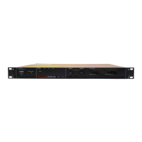
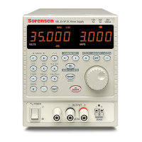
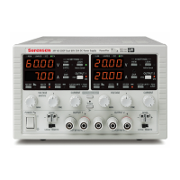
Front panel controls and indicators for the DHP Series are identified in Figure 3-1.
Although different models may have different heights, the controls remain the same
across the entire series. Table 3-1 provides a description of all operator controls and
indicators.
ENTER
0
.
9
6
3
8
5
2
7
4
1
CONSTANT VOLTAGE
REMOTE
CONSTANT POWER
CONSTANT CURRENT
OUTPUT: 10.00 VOLTS
100 AMPS
ON
OFF
MENU
VOLTAGE
CURRENT
OVERVOLT
LAST SET
CANCEL
1 2
3
4
Figure 3-1
DHP Series Controls and Indicators
Table 3-1
2U, 3U and 6U High Series Controls and Indicators
INDEX NO.
CONTROL/INDICATOR
FUNCTION
1
2
3
4
ON/OFF Switch
Alphanumeric Display
Status Displays
Control Keyboard
Turns power on or off to the supply.
Note: Standby power is present when
switch is in the off position.
Displays output voltage and current,
power supply status and other
information.
Display operating mode of power
supply.
Allows user control of power supply.
M550004-01
3-1

 Loading...


