Installation Guide | 3-3
Mechanical Installation
This section describes how to mount and connect gases to your WDG-V
sensor. This includes the following:
• Sample Inlet Probe Installation (Wall/Flange Mount)
• Sample Inlet Probe Installation (Floor Mount)
• Exhaust Tube Installation (optional)
• Sensor Mounting (Wall/Flange Mount)
• Sensor Mounting (Floor Mount)
• Remote Calibration Unit Mounting and Plumbing (optional)
Sample Inlet Probe Installation (Wall/Flange Mount)
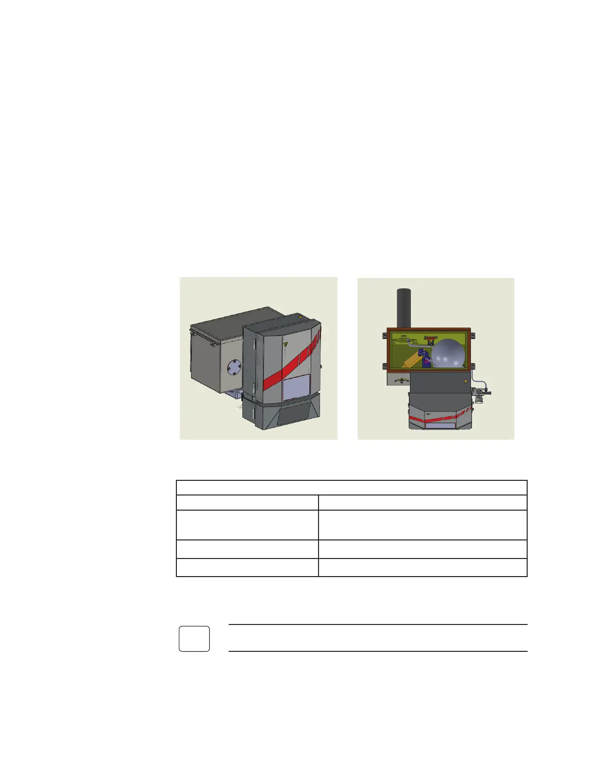
The WDG-V with Blow Back Option unit consists of a bolt-on attachment
to the standard WDG-V analyzer for use in high particulate applications.
Figure 3-1a and 3-1b. WDG-V with Blow Back and internal components.
Box Temperature is controlled to 150 ºC to keep above dew point.
Component Function
Accumulator Ball
Warms instrument air to avoid cold air blow
backs and condensation.
RTD in Box Alarms if temperature goes out of range.
Resettable Over-Temp Switch Prevents damage to internal components.
1. Using a standard 3”-300# mounting flange (shown in Figure 3-1b)
mount the analyzer to the process stack.
Other options for mounting are available.
 Loading...


