3-6 | Thermox WDG-V / VC / VCM with Blow Back
3. Screw coupler fitting into base. Figure 3-5b.
4. Install hook into compression fittings. Figure 3-5b.
5. Re-install Blow Back lid.
Pressure Adjustments (Floor Mount)
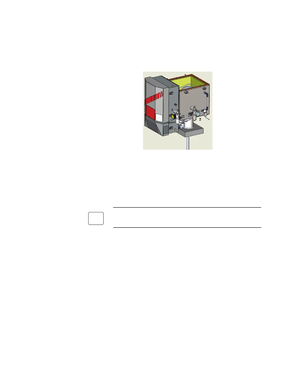
Figure 3-6. Pressure adjustment regulators.
1. Adjust sensor flow using the Aspirator - Regulator 1.
2. Adjust the Blow Back pressure using the Blow Back -Regulator 2.
3. Minimum instrument air supply pressure = 80 psi.
Exhaust Tube Installation
If installing an exhaust tube, you must connect it to the sensor before
mounting the sensor to the process.
An optional stainless steel exhaust tube is available (PN 70619KE), which
allows you to extend the aspirator exhaust.
To install the exhaust tube, thread the exhaust tube into the exhaust port
on the rear of the sensor.
 Loading...


