EasyManuals Logo

Ametek Thermox WDG-VCM User Manual

Ametek Thermox WDG-VCM
164 pages
To Next Page IconTo Next Page
To Previous Page IconTo Previous Page
Page #71 background imageLoading...
Page #71 background image
AMEVision Display User Interface or Communications | 4-3
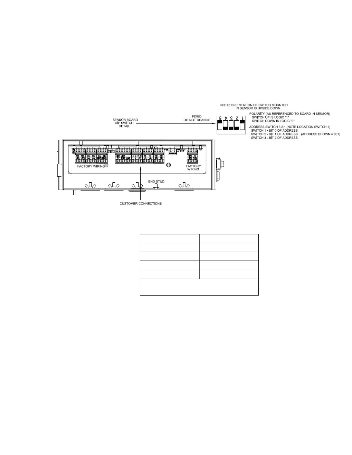
Setting the Analyzer Address
The interface bewteen the AMEVision Display User Interface and the
WDG-V sensor is a two-wire MODBUS RTU. Up to four WDG-V sensors
can be connected to a single AMEVision Display User Interface unit. Each
attached sensor must have a unique address. The address on the WDG-V
sensor is set via the dip switch on the front of the electronics PCB.
Figure 4-2. Dip Switch Locations
321 Switch Address
001 1
010 2
011 3
100 4
1 = ON (UP)
0 = OFF (DOWN)

Table of Contents

Questions and Answers:

Question and Answer IconNeed help?

Do you have a question about the Ametek Thermox WDG-VCM and is the answer not in the manual?

Ametek Thermox WDG-VCM Specifications

General IconGeneral
BrandAmetek
ModelThermox WDG-VCM
CategoryMeasuring Instruments
LanguageEnglish

Related product manuals