3-4 | Thermox WDG-V / VC / VCM with Blow Back
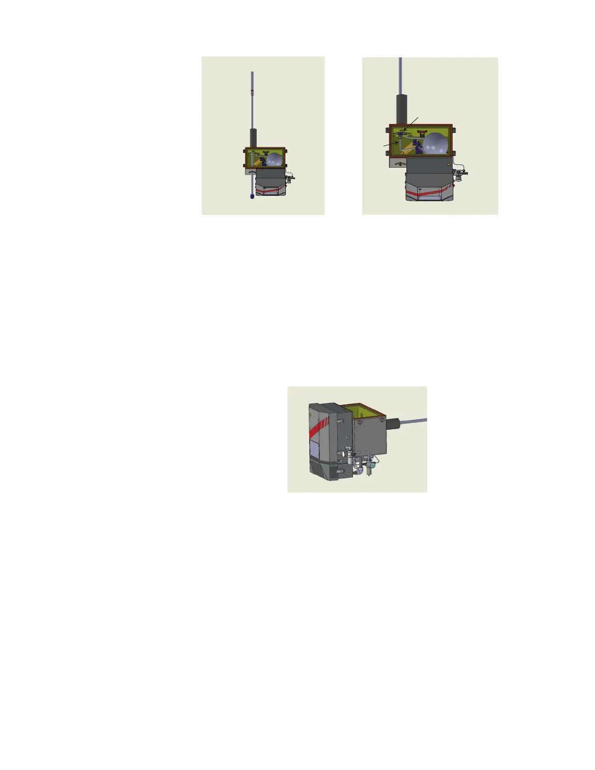
Coupler Fitting
Hook
Figure 3-2a and 3-2b. Probe installation.
2. Slide the probe and filter through door in the front of the blow back
enclosure. Figure 3-2a.
- Blow Back probe is ½” Schedule 40 pipe.
- Standard Blow Back filter is 316 SS, 2 micron porosity.
3. Screw in coupler fitting into back plate. Figure 3-2b.
4. Install hook into compression fittings. Figure 3-2b.
Pressure Adjustments (Wall/Flange Mount)
1
2
Figure 3-3. Pressure adjustment regulators.
1. Adjust sensor flow using the Aspirator - Regulator 1.
2. Adjust the blow back pressure using the Blow Back -Regulator 2.
3. Minimum instrument air supply pressure = 80 psi.
 Loading...


