Installation Guide | 3-5
Sample Inlet Probe Installation (Floor Mount)
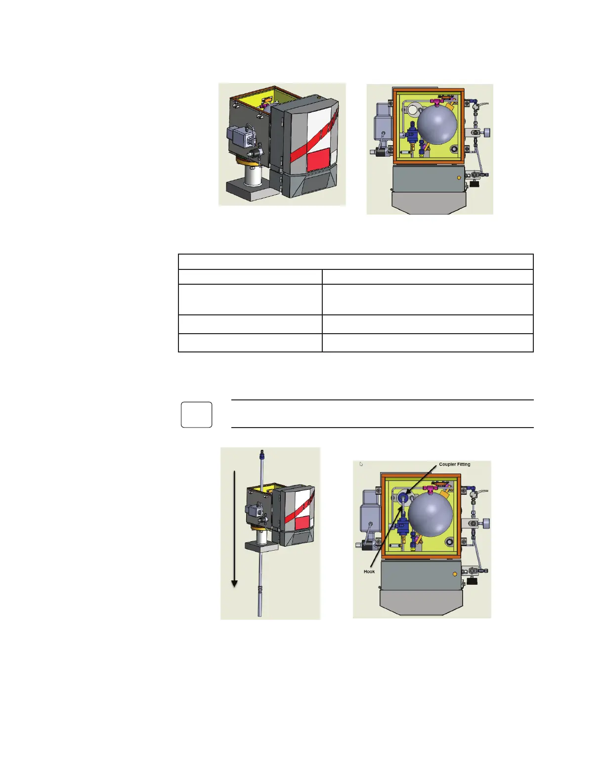
Figure 3-4a and 3-4b. WDG-V with Blow Back and internal components.
Box Temperature is controlled to 150 ºC to keep above dew point.
Component Function
Accumulator Ball
Warms instrument air to avoid cold air blow
backs and condensation.
RTD in Box Alarms if temperature goes out of range.
Resettable Over-Temp Switch Prevents damage to internal components.
1. Using a 3”-150# mounting flange and nipple supplied by AMETEK
(shown in Figure 3-4a) mount the analyzer to the process stack.
Consult the factory for other floor mount configurations.
Figure 3-5a and 3-5b. Probe installation.
2. Slide the probe and filter down through the probe opening. Figure
3-5a.
- Blow Back probe is ½” Schedule 40 pipe.
- Standard Blow Back filter is 316 SS, 2 micron porosity.
 Loading...


