0.6 (2019–07–25)
Amlogic Proprietary and Confidential
Copyright © Amlogic. All rights reserved.
50
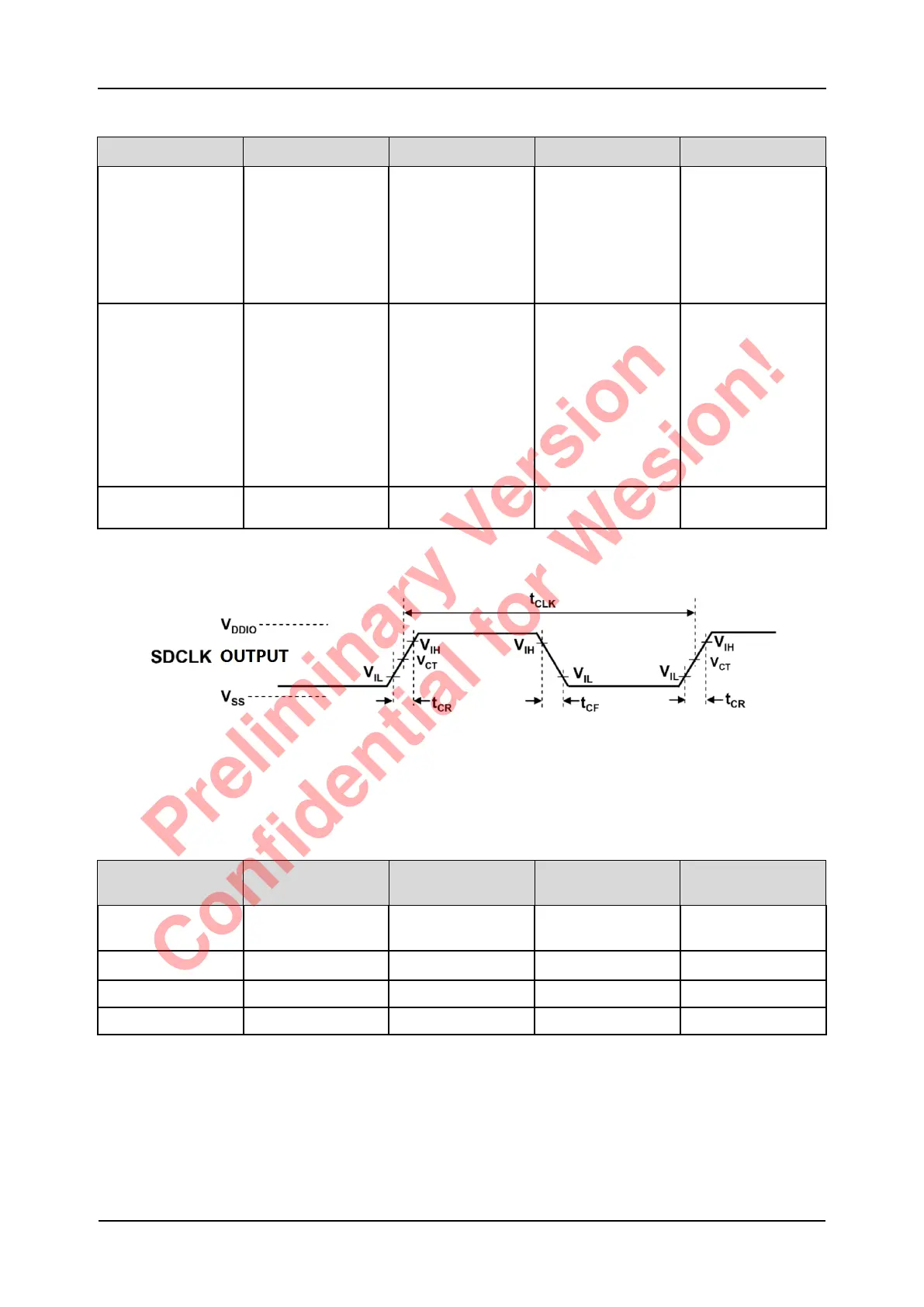
Table 5-5 HS200 Timing Specification
Symbol Parameter Min Max Unit
tPH Device output
momentary phase
from CLK input to
CMD or DAT line
output.
Does not include a
longterm
temperature drift.
0 2 UI
ΔTPH Delay variation due
to temperature
change after tuning.
Total allowable shift
of output valid
window (TVW) from
last system Tuning
procedure ΔTPH is
2600ps for ΔT from
-25 °C to 125 °C
during operation.
-350(ΔT=-20deg.C) 1550(ΔT=90deg.C) ps
tVW Valid Data Simple
window
0.575 - UI
Figure 5-6 SDIO (SDR104) Clock Signal Timing Diagram
Table 5-6 SDIO (SDR104) Clock Timing Specification
Symbol Parameter (SDR104
Mode)
Min Max Unit
tCLK clock period Data
Transfer Mode (PP)
4.8 - ns
Duty Clock Duty 30 70 %
tCR clock rise time - 0.96 ns
tCF clock fall time - 0.96 ns
S905D3 Quick Reference Manual 5 Operating Conditions
Preliminary Version
Confidential for Wesion!