0.6 (2019–07–25)
Amlogic Proprietary and Confidential
Copyright © Amlogic. All rights reserved.
59
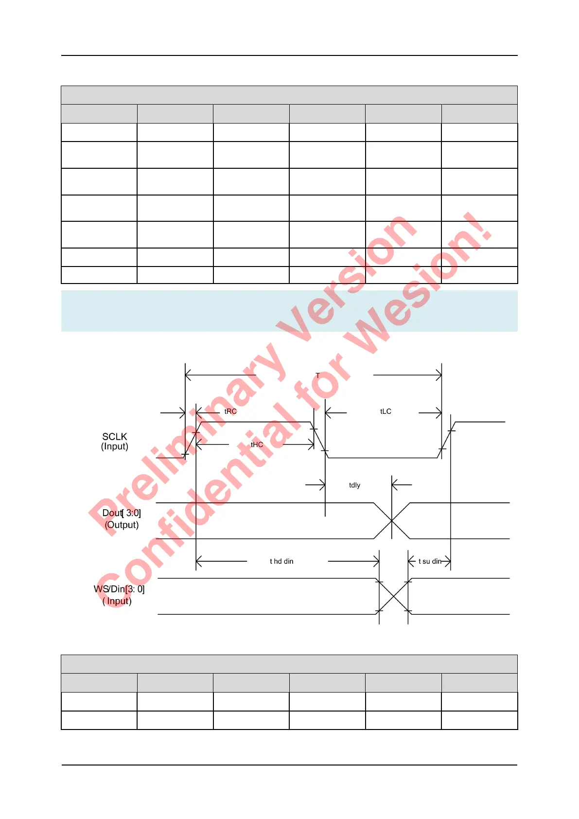
Table 5-15 Audio I2S/TDM Timing Specification, Transmitter, Master Mode
Transmitter (master mode)
Symbol Parameter Min Typ Max Unit
T Clock period 10 ns
tHC High level of
SCLK
0.4 T
tLC Low level of
SCLK
0.4 T
tRC Edge time of
SCLK
0.8 ns
tdly Delay from
SCLK to WS
-2 3 5
tsuin Setup time of Din 4 ns
thdin Hold time of Din 4 ns
Note
Measure Pointrefers to VIH, ViL parameter of Normal GPIO Specifications.
Figure 5-19 2S/TDM Timing Diagram, Slave Mode
Transmitter (slave mode)
Symbol Parameter Min Typ Max unit
T(out) Clock period 40 ns
T(in) Clock period 10 ns
S905D3 Quick Reference Manual 5 Operating Conditions
Preliminary Version
Confidential for Wesion!