2-2 General Operation Chapter 2 — Functional Description
2-2 PN: 13000-00164 Rev. K ML248xx, ML249xA MM
2-2 General Operation
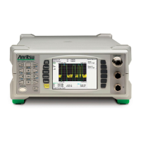
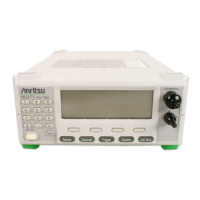
The power meter consists of several key blocks.
Input Amplifier
Each sensor input has its own dedicated, low noise, high speed amplifier. The CW amplifier is split into five
ranges to cover the power range from –70 dBm to +20 dBm. Ranges 1 to 2 are DC coupled. Ranges 3 to 5 are
used for low-level measurements. These are the AC ranges and are used in conjunction with a chopper located
in the sensor.
Ranges 7, 8 and 9 are high speed ranges and split the signal into two paths; a wideband AC path and a DC low
bandwidth path. The two sections are recombined before a high speed ADC for Pulse Mod measurements
which samples at 64 Ms/s.
Signal Processing
The signal processing is split between two functional blocks; the dedicated FPGA, and the DSP.
FPGA
The FPGA controls the AD converters. Data is sampled at a rate determined by the capture time set for the
measurement. The highest sample rate is 64 Ms/s. The data is stored in a 256K trace memory buffer. Internal
and external triggers are handled by the FPGA.
Digital Signal Processor (DSP)
A dedicated processor is used to control all signal processing including measurement processing, sensor
interface, internal channel calibration, zeroing, averaging, and communication to the main processor. The
256K trace buffer memory is dual port and is accessed by the DSP for signal processing. Results are then
passed to the main processor that handles the display and remote interfaces. When the power meter is turned
on, the main processor downloads the DSP operating program that runs a self-test and confirms all hardware
is operational.
2-3 Interface
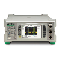
The power meter front panel has a 1/4 VGA LCD unit. The front panel has three sets of keys.
2-4 GPIB Operation
The power meter GPIB operation is provided by a fully integrated National Instruments TNT 4882 IC. Most
front panel functions are available by GPIB command. These commands are fully described in the Remote
Programming Manual.
2-5 Case Construction
The power meter has a clamshell case structure. The top and bottom covers are of a rugged molded plastic
construction. The top case has raised slots that align with the feet of the bottom case to allow unit stacking.
The front and rear panels are fitted into slots in the top and bottom cases.
Numeric keypad Used to scroll down menus, enter numeric values and move markers.
Hard keys Used to select menus for the operation of the power meter.
Soft keys Used to select dialog boxes and instrument settings.
 Loading...
