ML248xx, ML249xA MM PN: 13000-00164 Rev. K 3-1
Chapter 3 — Performance Verification
3-1 Introduction
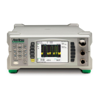
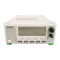
Performance of the Anritsu ML248xA, ML248xB and ML249xA Power Meters can be verified using the
procedures in this chapter.
3-2 Test Conditions
The equipment used to verify the power meter is intended for use as calibration instruments, and as such must
be operated under controlled conditions of temperature and humidity in order to meet its specified precision
and stability.
All tests must be performed at a temperature of 25 °C ±10 °C (77 °F ±18 °F) and a relative humidity of less
than 75 % at 25 °C (77° F), non-condensing. Prior to making any precision measurements, allow the range
calibrator and the power meter to warm up for a period of 15 minutes from power on. If the power supply is
interrupted for any reason, allow a similar settling period.
3-3 Measurement Uncertainty
All test records are provided with a measurement uncertainty, which consists of the type-B
1
components. The
error contributions are measurement method, test equipment, standards, and other correction factors (for
example, calibration factors and mismatch error) per the prescribed test procedure. The statement(s) of
compliance with specification
2
is based on a 95 % coverage probability for the expanded uncertainty of the
measurement results on which the decision of compliance is based. Other values of coverage probability for the
expanded uncertainty may be reported, where practicable, for some of the measured values it is not possible to
make a statement of compliance with specification
2
.
3-4 Input Range Verification
The performance of the power meter’s individual signal channel inputs are verified using the Anritsu
ML2419A Range Calibrator. Ranges 1 through 5 are verified on the ML248xA power meter, while ranges
1 through 5, and 7 through 9 are verified on the ML248xB and ML249xA power meters. References in this
procedure to sensor input B apply to model ML2488A, ML2488B or ML2496A (dual-channel) power meters
only.
Required Equipment
• Anritsu ML2419A Range Calibrator
Measurement Procedure
1. Connect the range calibrator to the power meter using 1.5m sensor cables. The input(s) to be verified
must be connected to the corresponding connector(s) on the range calibrator. Connect power meter
connector A to range calibrator connector A, and power meter connector B to range calibrator
connector B (ML2488A, ML2488B or ML2496A only).
2. On connection of the sensor cable(s), the meter automatically detects a range calibrator is present and
displays the performance verification menus.
1. BIPM JCGM 100:2008 Evaluation of measurement data–Guide to the expression of uncertainty in measurement
2. LAC–G8:03/2009: Guidelines on the Reporting of Compliance with Specification
 Loading...
