2-8 Front Panel Connectors Chapter 2 — Functional Description
2-4 PN: 13000-00164 Rev. K ML248xx, ML249xA MM
Data Entry Keypad
The data entry keypad features the numbers 0 to 9 and all the letters of the alphabet. The keypad also allows
the user to enter a positive or negative value and enter a decimal point. These keys are used to enter numeric
data, such as a sensor cal factor frequency.
ON/Standby Key
The On/Standby key is used to turn the unit on from standby mode. The switch is a software control switch
that indicates to the PSU control circuitry what state the unit should be in. The power meter is in standby
mode when AC line power is applied.
2-8 Front Panel Connectors
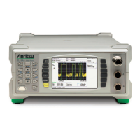
This section describes the power meter front panel connectors.
Sensor Inputs
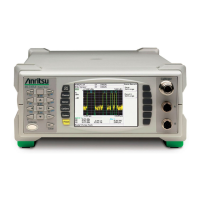
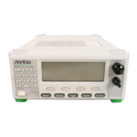
On standard model power meters, the signal channel A and B input connectors are mounted on the front panel.
The connectors are 12-pin Hirose type. A sensor cable, provided with the meter, is used to connect an Anritsu
power sensor to the signal channel. The connectors are snap push fit and require the outer body to be pulled to
enable removal.
RF Reference Calibrator
The internal reference provides a high stability, high accuracy level for signal channel calibration. The output
connector is a flange mounted female ‘N’ type. With the power sensor connected to the calibrator output, a
“Zero/Cal” will automatically zero the signal channel and then perform a 0 dBm calibration. All measurements
are then referenced to the 0 dBm level.
2-9 Rear Panel Connectors
This section describes the power meter rear panel connectors.
Line Power Input
The AC line power input module is mounted on the rear panel and the supplied line power cable connects to it.
The module contains filtering elements to ensure immunity to external noise and reduce emissions. The power
meter automatically senses the line level and internally configures itself accordingly. The specified line power
requirement is 85 to 264V AC, 47 to 440 Hz, 80 VA maximum. An internally mounted 2.5A slow blow fuse
provides fault protection.
Ground Stud
A ground stud provides an additional grounding connection.
RS-232 Port
A PC standard 9-pin D connector provides connection to the serial port. The serial port can be used to update
the power meter operating firmware, and control operation of the power meter from a PC or terminal. The
hardware handshake lines RTS and CTS are used to control the flow of data.
Note The internally mounted 2.5 A slow blow fuse cannot be changed by the operator.
 Loading...
