6-2 Power Meter Disassembly Chapter 6 — Removal and Replacement Procedures
6-8 PN: 13000-00164 Rev. K ML248xx, ML249xA MM
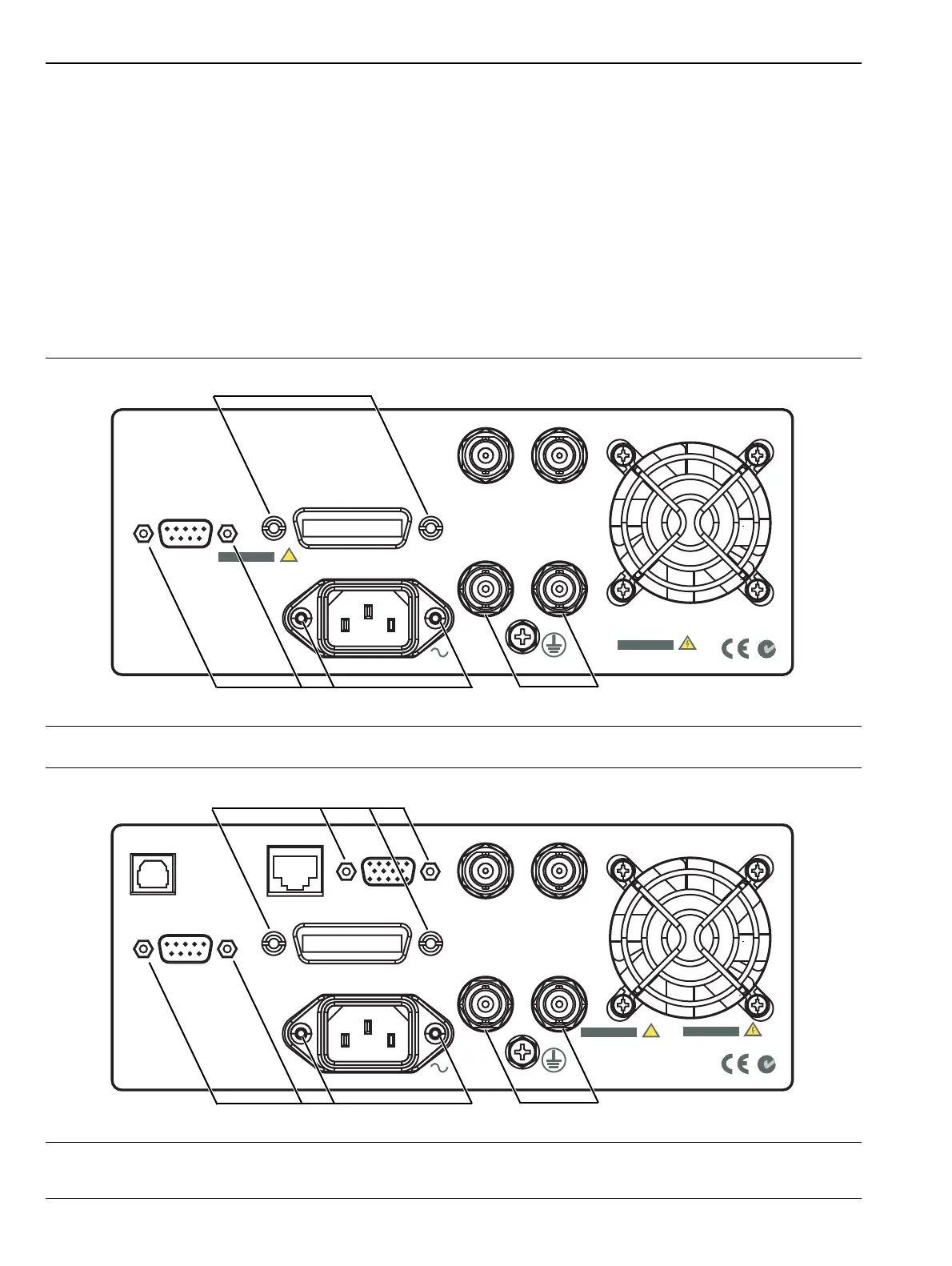
Rear Panel Removal
The rear panel is removed from the main control PCB. See Figure 6-10 or Figure 6-11, depending on model.
1. Remove the two screws that hold the line power input module to the rear panel. Undo the nut that
secures the earth cable to the rear panel stud. Remove the module.
2. Remove the fan cable from J400 on the control PCB assembly.
3. Remove the lock nuts from BNC Output 1 and BNC Output 2. Remove the lock washers.
4. Remove the two screws and washers from the GPIB connector. Remove the two nuts from the connector
on the main PCB.
5. Remove the two screws and washers from the RS-232 connector. The rear panel is now free.
6. Remove the screws and nuts at the locations shown below.
Figure 6-10. Rear Panel Removal (ML248xA)
Figure 6-11. Rear Panel Removal (ML248xB and ML249xA))
Remove Nuts
Model ML248xA
Remove Screws and Nuts
Remove Screws
System RS232
GPIB / IEEE 488
85-264VAC
47- 440 Hz
80VA Max
Output 2Output 1
V/GHz Input
External Trigger
NO OPERATOR SERVICEABLE
PARTS INSIDE
WARNING
DO NOT OPERATE WITH
UNGROUNDED POWER CORD
WARNING
!
Remove Nuts
Models ML248xB and ML249xA
Remove Screws and Nuts
Remove Screws and Nuts
System RS232
GPIB / IEEE 488
85-264VAC
47- 440 Hz
80VA Max
Output 2Output 1
V/GHz Input
External Trigger
Ethernet
USB
NO OPERATOR SERVICEABLE
PARTS INSIDE
WARNING
DO NOT OPERATE WITH
UNGROUNDED POWER CORD
WARNING
!
VGA Out

 Loading...


