The provided document is a hardware and software manual for the GT3000 Drive from Answer Drives S.r.l. It details installation, operation, maintenance, and programming aspects of the drive.
Function Description
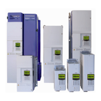
The GT3000 drives are designed for a wide range of applications requiring constant adjustment of motor speed. They are compact, reliable, cost-effective, efficient, and user-friendly, suitable for various three-phase motors. The advanced digital control system offers extensive programming options. The GT3000 LARGE series can be supplied with either AC or DC power. These drives support single or multi-motor applications with asynchronous motors and are available in 6-pulse (K), 12-pulse (P), or 18-pulse (R) harmonic distortion versions, or with Active Front End (AFE) control.
The drive offers three main control modes:
- Scalar Control (V/F): Provides voltage-frequency regulation with constant or variable ratio. It includes voltage boost and operates in open-loop, with a limited speed regulation range of 1:15. Typical applications include fans, centrifugal pumps, conveyor belts, and roller conveyors.
- Sensorless Control (SLS): Offers independent torque and flow control (similar to a DC motor). It features good static and dynamic performance and operates in closed-loop (simulated), with a speed regulation range of 1:50 and a speed resolution of 1:1.000. It includes slip compensation, with a typical static speed accuracy of 0.2 x fslip (less than 0.2% for speed control range 5-100%, and approximately 1% for speeds below 5%). Output current control is available, with a torque control response of less than 5 ms. Typical applications include extruders, presses, and positive-displacement pumps.
- Vector Control (FOC): Also provides independent torque and flow control (similar to a DC motor) but requires an encoder. It offers excellent static and dynamic performance and operates in closed-loop, with a speed regulation range of 1:1.000 and a speed resolution of 1:5.000. Static speed accuracy is 0.01%. Torque control is available even at zero speed, with a torque control response of 5 ms. This mode is suitable for hoisting and lifting equipment, shearing machines, and coordinated devices.
The GT3000 also includes various application macros for specific functionalities such as DC braking, current oscillation compensation, jog, speed external limits, energy saver, emergency stop, helper (master-slave), pope, drooping, tension regulator with load cells, torque control, torque limits control, motor stall, speed deviation, torque overboost, trace settings, AND/OR functions for DI/DO, auto start, crane brake control, analog input user trip/alarm, safety override, and back-lack compensation.
Important Technical Specifications
General Data:
- Standards: IEC 146.2, EN61800-3 (EMC), EN 50178 (low voltage), UL and cUL certification.
- Operating Temperature: 0-40°C (1% current derating for every °C, max 55°C).
- Storage Temperature: -25 to +70°C.
- Relative Humidity: 95% (without condensation).
- Altitude ASL: 1000m (1% current derating for every 100m, max 3000m).
- Protection Grade: IP20 for Frames I-IIIN, IP00 for Frames VII-VIII (IP20 optional).
- Cooling: Integral fan.
- Three-phase voltage: F/M=380-480V (G/N=500V)±10%, K/P=690V ±10%.
- Frequency: 48-63Hz.
- DC bus: Y=510-650Vdc (Z=675Vdc), J=710-930Vdc.
- Power factor: Total 0.93 to 0.96, Fundamental mode >0.98 (with line reactor).
- Efficiency: >0.98 (50Hz-rated load).
- Output Frequency: 0.1-200Hz.
- Switching Frequency: 2-12 KHz.
- Frequency Resolution (V/Hz): 0.1Hz.
- Frequency Accuracy (V/Hz): 0.1% (analog control), 0.01% (digital control).
- Speed Resolution: 1:5000 (FOC).
- Speed Static Accuracy: 0.01% (FOC).
- Torque Control Response Time: 5ms (FOC).
- Overload: Class 1: 110%x60s every 10 min; Class 2: 150%x60s every 10 min.
- Microprocessor Cycle-Time: 250 µs.
Control Connections:
- Analog Inputs: 2 differential (12Bit), configurable (0-10V, 0-±10V, 0/4-20mA).
- Analog Outputs: 2 (10Bit), 0-10V adjustable and configurable (current, motor voltage, frequency/speed, power, etc.).
- Digital Inputs: 6 optoisolated (4 configurable), 2 terminals configurable as logic and programmable inputs/outputs.
- Relay Outputs: 1 relay-type output (NA): DRIVE OK, 1 relay-type output (NA), 1 relay-type output (NA+NC).
- Static Output: 1 (24Vdc) running, minimum frequency, attained frequency, torque threshold, brake control, etc.
- Encoder Input: Three-channel.
Cooling Specifications:
- GT3000 drives (except SVGT0P3 to 0P6) include an internal fan with air intake from the bottom.
- Cooling fan rated data (voltage and current) are provided for various drive models. For example, SVGT125F/Y, SVGT150F/Y, SVGT166F/Y use 230V 50/60Hz, 0.9A fans. Larger frames like SVGT200F/Y, SVGT250F/Y use 230V 50/60Hz, 1.45A fans. Even larger frames like SVGT292F/Y to SVGT940M/Y use 400V/50Hz - 440V/60Hz, 3.4/4.4A fans, often with multiple fans.
Dynamic Braking:
- Braking units are available for most GT3000 drives (except SVGT340-780).
- The braking unit is necessary when braking torque exceeds 15% of the motor's nominal torque, with a maximum allowed braking torque of 150% of motor rated torque.
- Braking resistors are selected based on formulas provided, considering drive type, inertia, load torque, and deceleration time.
- Braking voltage depends on the drive voltage class (e.g., 750V for 380-480V class, 1090V for 525-690V class).
RFI Filters and Reactors:
- Input line reactors are recommended for transient protection, reducing RMS ripple currents, improving power factor, and reducing harmonics.
- Output reactors are used to compensate for capacitive dispersion current and reduce voltage gradients at motor terminals, helping with RFI attenuation.
- Sinus filters suppress high-frequency components of the output voltage, making the motor voltage waveform almost sinusoidal. They are particularly useful for motors with inadequate insulation, submersible pumps with long cables, and EX applications.
Usage Features
Installation:
- Drives must be handled carefully during receiving, unloading, unpacking, and inspection.
- Storage should be in a dry, weather-protected, and temperature-controlled area.
- Mechanical installation requires vertical mounting, free from vibrations, dust, metallic particles, and corrosive liquids.
- Clearances around the drive are specified for proper air circulation and maintenance access (e.g., 25mm for I-II frames, 50mm for III-IVN frames, 100mm for VN-VIL frames, and 50mm for VII-VIII frames).
- Hot air recirculation must be prevented, either by leading exhaust air away or using leak-proof air baffles inside the cabinet.
- Accessing terminals involves removing covers, with specific instructions for different frame types.
- Electrical installation requires qualified technicians, adhering to safety precautions like lockout/tagout procedures, verifying DC link voltage discharge, and proper grounding.
- Power wiring diagrams are provided for 6-pulse and 12/18-pulse SVGT drives, including connections for braking resistors, input reactors, and output reactors.
- Detailed tables specify power cable and fuse sizing based on drive model, supply, and current ratings.
- Auxiliary power supplies for control boards and fans are detailed, including jumper settings for voltage selection.
- Encoder connection instructions are provided for both SCADA BASIC and SCADA PLUS boards, including jumper settings for power supply and line driver/push-pull configurations.
- An installation checklist ensures all mechanical and electrical aspects are verified before start-up.
Programming:
- The manual covers programming tools, including basic and advanced keypads, menu system, and PC interface (RS485 Multi-Drop Functionality, TELEASSISTANCE).
- It outlines programming levels (Level 1: Quick Motor Start-Up, Level 2: Quick Application Start-Up, Level 3: Advanced System Application) and motor control modes (V/Hz, Sensorless, FOC).
- Standard macros are available for various functions like speed demand, preset speeds, digital potentiometer, speed command loss, critical speed avoidance, ramps, VDC rollback, current rollback, motor overload thermal protection, free run stop, auto reset & restart, HOA/pulsed start stop, auto on/off, input single phasing, VDC under voltage ride through, flying restart, energy saver, and external PID regulator.
- Diagnostics, protections, and troubleshooting information are provided, including drive trips, alarms, fault/alarm log, real-time clock, and a list of protections.
Options:
- Braking Unit: External braking units (GTBU) are available for installation outside the drive, with specific models and resistor values.
- Keypads: Three types are available: SVGTBFK (LED-type), SVGTAFK (LCD-type, graphic, backlit), and a remote keypad kit for enclosure door mounting.
- External Control Power Supply: An external power supply is needed to keep the field bus fed when the drive is not powered and to monitor the drive in safety.
- SIOVA Digital I/O Expansion Board: Provides 8 isolated digital inputs (24V) and 8 relay digital outputs, requiring an external 24Vdc power supply. It can be installed inside the drive (Frame VII and VIII) or outside.
- Safe Stop Board: Ensures the "SAFE TORQUE OFF" function, preventing motor rotation and torque generation. It complies with EN 60204-1 and EN 954-1 safety requirements.
Maintenance Features
Preventative Maintenance:
- Keep it clean: Dust on hardware can reduce airflow and cause malfunction. Use oil-free and dry air for cleaning.
- Keep it dry: Moisture contributes to failure.
- Keep connections tight: Heat cycles and mechanical vibration can loosen connections.
- Periodic checks: Inspect wires for damage, ensure terminals are tight, verify ambient temperature, check for dust/condensation on boards, insulation integrity, and unobstructed vents/fans.
- Electronic Boards: Do not require specific maintenance, but dust should be removed without compressed air. Handle with electrostatic discharge (ESD) precautions.
- Heatsink: Periodically remove dust.
- Fans: Average life is 3-4 years (at 35°C, 20 operating hours/day). Increased noise or temperature are signs of failure.
- Capacitors: Average life is 5-6 years (at 35°C, 20 operating hours/day).
- Capacitor Reforming: For drives stored or unused for more than two years, capacitor reforming procedures (Method 2A or 2B) are detailed to prevent damage upon energization. This involves connecting a rectifier and resistor circuit or a DC power supply to the converter's DC link.
Safety Precautions:
- All maintenance and installation must be performed by qualified technicians.
- Strict adherence to electrical safety procedures is mandatory, including lockout/tagout, verifying power disconnection, waiting for capacitor discharge, and using appropriate safety gear.
- IGBT modules are sensitive to electrostatic charges and must be handled with care.
- The manual provides instructions for testing input/output bridges using a digital multimeter.
- Optical fiber cable tests are described to check for breaks or malfunctioning transmitter/receiver.
Software Download:
- A step-by-step procedure for downloading software to the microprocessor Plus board is provided, including using the "flashp165" program, connecting via RS232, closing/opening jumpers, and resetting the drive.
- Warnings are given regarding repeated reset operations during initialization and the need to program application values after download.
Spare Parts:
- A comprehensive list of spare parts is provided, including control boards, power supply boards, AC reactors, pilot boards, IGBT modules, capacitors, RFI filter boards, fans, rectifiers, charge resistors, precharge thyristors, snubber boards, current transducers, and brake units.
- Suggested quantities for single drives are indicated.