IMGT30017EN 47
4A. MAINTENANCE
4A.1 Operating principle
The most important components of GT3000 are the following:
• I
NPUT POWER TERMINALS • MICROPROCESSOR BOARD
• I
NPUT RECTIFIER CIRCUIT • KEYPAD DISPLAY MODULE
• P
RECHARGE • GATE DRIVE INTERFACE BOARD
• DC
BUS CAPACITORS • POWER IGBT MODULES
• O
UTPUT POWER TERMINALS
Note: AC input terminals and input rectifier are not needed in DC Bus applications. For some control applications the Keypad and/or the
Microprocessor board may not be installed.
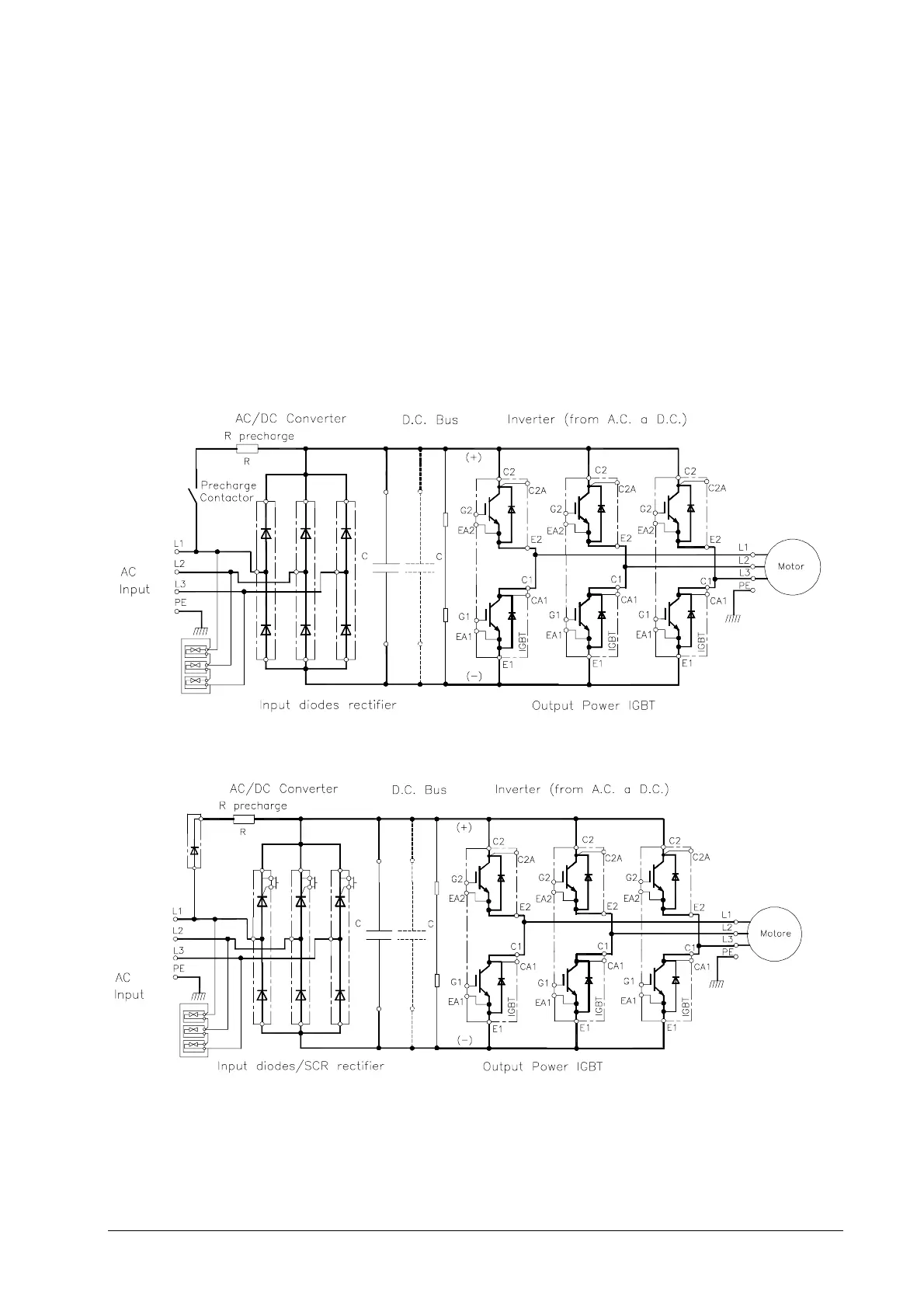
An electrical diagram of GT3000 is illustrated in Figure 5A.1. The drive consists of three main sections:
• Converter section: it converts the fixed-frequency input AC voltage into a DC voltage
• DC Bus: it is composed of capacitors, used to filter the associated line ripple and store energy
• Inverter section: it is composed of IGBTs modules that are controlled to convert the DC voltage into a three-phase AC output
voltage that varies in frequency and amplitude, and is used to control the connected motor.
Figure 4A.1.1 Diagram of GT3000 Drive (0P3F – 036F)
Note: precharge contactor in some sizes is on negative DC supply – refer to power schematics in Appendix A.
Figure 4A.1.2 Diagram of GT3000 Drive (045F – 960K)