Braking Unit GT3000
58 IMGT30017EN
External braking units suitable for installation outside the drive and designated “GTBU .. F/K” are also available.
(See STAND ALONE BRAKING UNIT MANUAL IMGT30006EN/IT
Table.6A.2.2.GTBU. External braking module for drives
Drive BRAKING Resistor Cont. power Resistor Dimensions
UNIT Min. value Switch Typical @ 400V W H D
Type
Type SAP code
Rb
[kw]
KW SAP code mm mm mm
Rated voltage 380V - 480V ±10%
GTBU062F 1000001482
10
15 10 4
ELC40950304
127 341,5 318,5
GTBU150F 1000001481
5
10 5 8
ELC40950405
127 341,5 318,5
SVGT340-470F
GTBU420F 1000000994
1,1
* On request On request
302 370 313,5
SVGT520-580F GTBU580F 1000000992
0,8
* On request On request
302 370 313,5
SVGT670-940M GTBU780F 1000003065
1,1 + 1,1
* On request On request
2x302 2x370 2x313,5
Rated voltage 525V - 690V ±10%
SVGT260-320K
GTBU320K 1000003057
3
* On request On request
302 370 313,5
SVGT390-480K
GTBU480K 1000003058
2,2
* On request On request
302 370 313,5
SVGT531-640K GTBU640K 1000003059
1,9
* On request On request
302 370 313,5
SVGT780-960K GTBU960K 1000003060
2,4 + 2,4
* On request On request
2x302 2x370 2x313,5
Models GTBU420-780F and GTBU320-960K require 24Vdc 0.5A external power supply.
* Sized for emergency braking (1.5 IN –Cl.2 for 60 s)
6A.2.2 Braking Resistor Installation and Wiring
The braking resistor must be installed outside the drive in a place where they will cool.
Warning! The materials near the brake resistor must be non-flammable. The surface temperature of the resistor is high. Air
flowing from the resistor is on the order of hundreds of degrees. Protect the resistor from contact.
Each resistor must be protected by an adequate temperature relay that opens the mains remote control switch when
triggered.
Use the cable type used for drive input cabling (refer to chapter1A) to ensure the input fuses will also protect the resistor cable. Alternatively, two
conductor-shielded cable with the same cross-sectional area can be used. The maximum length of the resistor cable(s) is 5 m (16,5 ft). For the
connections, see the power connection diagram of the drive.
The power rating of the resistor is not selected for duty-cycle 1. The drive will not be able to interrupt the main supply if the chopper remains conductive
in a fault situation so the resistor is connected to the mains directly through the rectifier bridge.
In such a situation, the resistor heats up to abnormally high temperatures, which could result in resistor failure. To prevent resistor failure, a suitable
thermal switch must protect the resistor. The thermal switch cable must be shielded and not longer than the resistor cable.
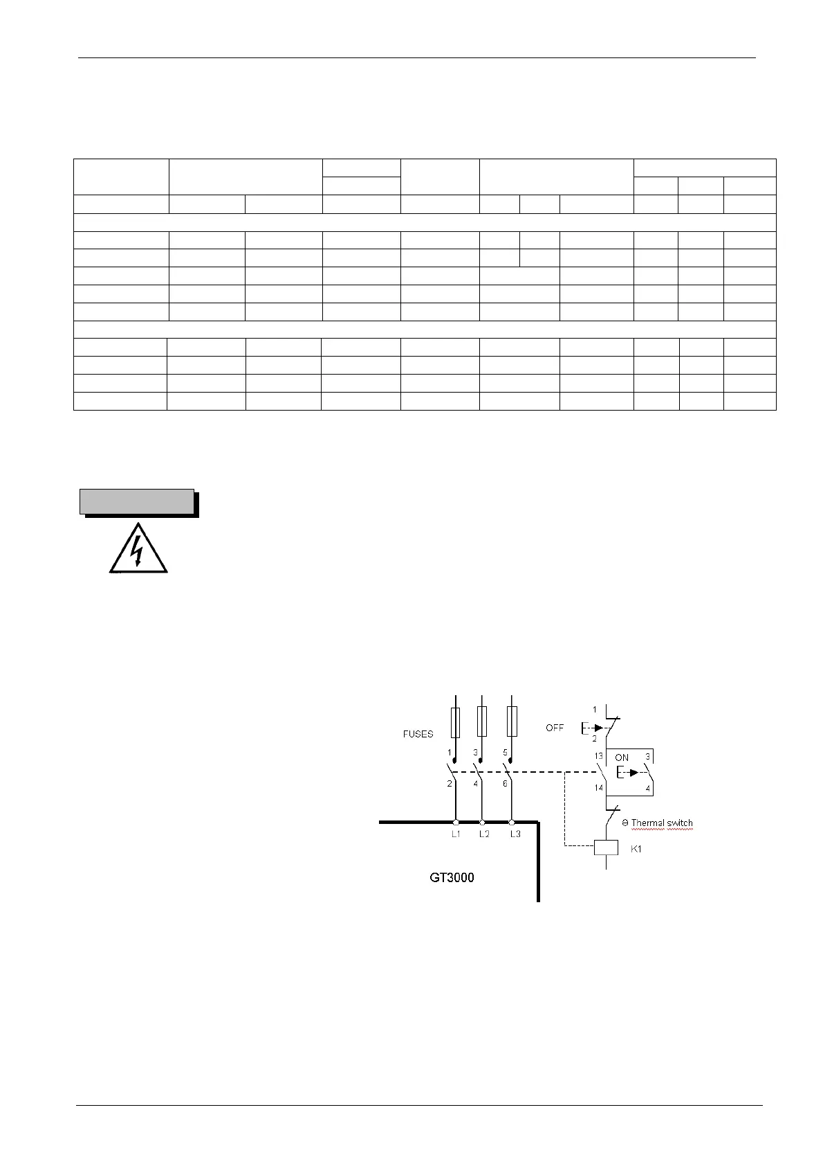
It is essential, for safety reason, to equip the drive with a
main contactor. Wire the contactor so that it opens in case
the resistor overheats.
Figure 6A.2 shows a simple example-wiring diagram.
Figure 6A.2. Simple Braking Resistor Wiring Diagram
6A.2.3 CHOOSING THE RESISTOR
When the speed (frequency) of an asynchronous motor decreases rapidly, the motor operates as an asynchronous generator and feeds energy back to
the drive. Some energy is dissipated into the motor (torque corresponding to about 10-20% of the motor rated torque). The remaining energy is
accumulated in the capacitors of the drive intermediate circuit with a voltage increase at their ends.
A dynamic braking unit is used to prevent the capacitor from reaching too high voltages that may result in drive shutdown.
An electronic circuit detects the voltage across the drive dc capacitor bank, and when this voltage exceeds a predefined value, the power transistor of
the braking unit is enabled. This activates the braking resistor in parallel to the drive dc capacitor bank.
As soon as the dc voltage goes back to its normal value, the power transistor is disabled.
CAUTION !