IMGT30017EN 81
APPENDIX A1 TERMINAL BOARDS AND POWER SCHEMATICS
This section contains the mechanical drawings of all frames of drives.
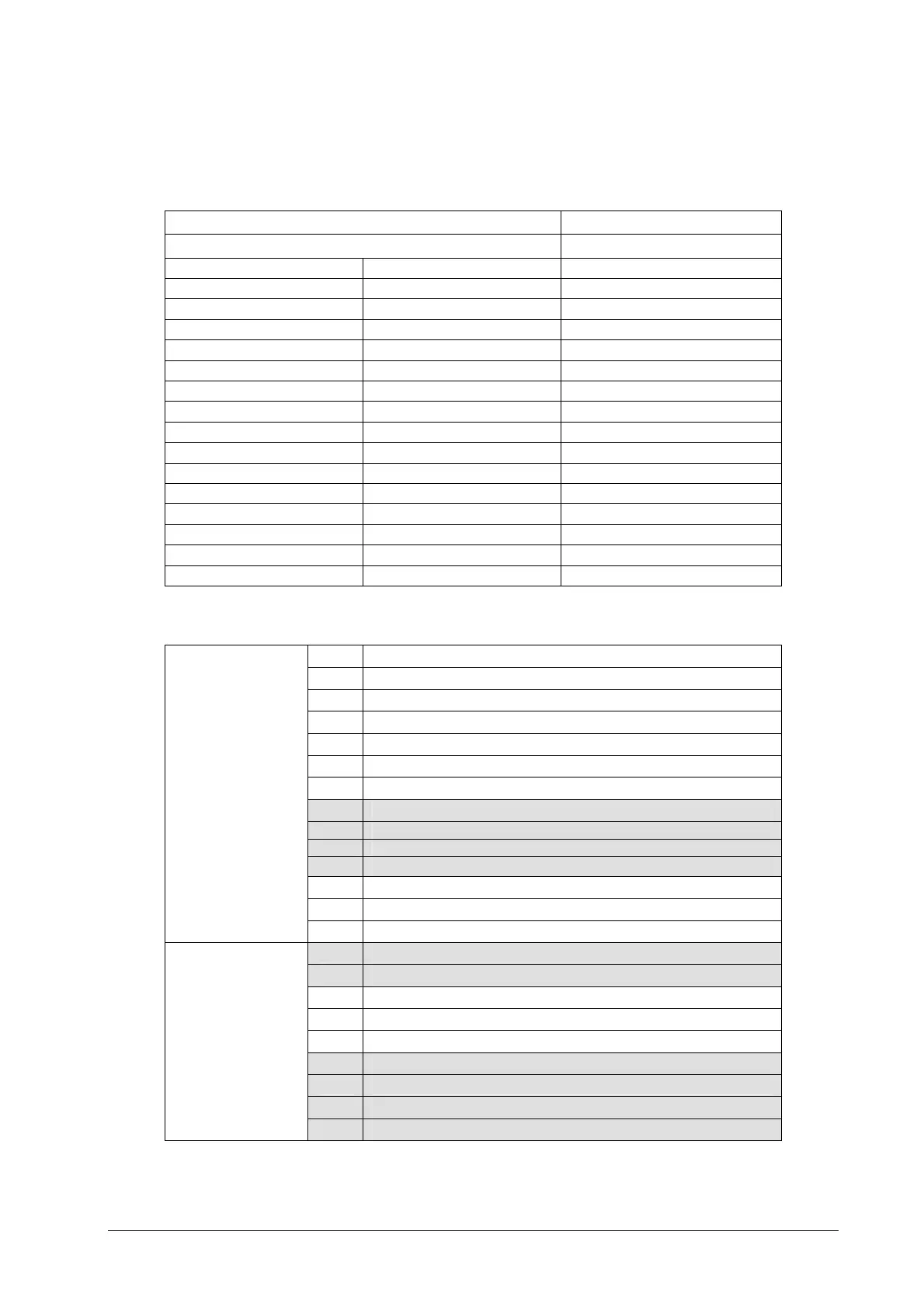
The following table shows the list of all attached drawings
FRAME/SIZE DRAWING
Pag.
FRAME I SVGT0P3/0P4F/0P6F 80
FRAME II-III-IIIX SVGT008/011/015/016/022F 81
FRAME IIIL SVGT028F 82
FRAME IVN SVGT030-036F/ 83
FRAME VN SVGT045/053/066F/Y 84
FRAME VIN SVGT076/108F/Y 85
FRAME VIN SVGT125/166F/Y 86
FRAME VI L SVGT105/130/170K/J 87
FRAME VII SVGT200-250F/Y 88-89
FRAME VIII SVGT292-340-420-470F/Y 90-91
FRAME 2xVII-VIII SVGT520-580-670-780F/Y 92-93
FRAME VII-VIII SVGT200-260-320K/J 94-96
FRAME VII-VIII SVGT390-521K/J 95-96
FRAME 2xVII-VIII SVGT640K/J 97-99
FRAME 2xVII-VIII SVGT780-960K/J 98-99
FRAME 2xVII-VIII Open frames SVGT003-028 100
Symbols used to indicate auxiliary and power terminals:
L1 Input phase – MAINS
L2 Input phase – MAINS
L3 Input phase – MAINS
PE Earth / Shields/Ground
U Output phase - U – MOTOR
V Output phase - V – MOTOR
W Output phase - W – MOTOR
RE + External braking resistor
RE - External brakin
resisto
RE1 + External brakin
resisto
RE1 - External braking resistor
+ Positive DC BUS
- P Negative DC BUS (Diode bridge)
Power terminal block
- Negative DC BUS (IGBT)
LV1 Auxiliary 230V-50/60 Hz
LV2 Auxiliary 230V-50/60 Hz
LV1 Auxiliary 380-50Hz/440V-60 Hz
LV2 Auxiliary 380-50Hz/440V-60 Hz
LV3 Auxiliary 380-50Hz/440V-60 Hz
LF1 Auxiliary 230V-50/60 Hz (K/J or F/Y with suffix 10 Control power supply)
LF2 Auxiliary 230V-50/60 Hz (K/J or F/Y with suffix 10 Control power supply)
XM10 Prech. OK (for SVGT200-940Y and SVGT200-780J only)
Auxiliary terminal block
XM11 Prech. OK (for SVGT200-940Y and SVGT200-780J only)