IMGT30017EN 111
APPENDIX A3 Instructions for the connection of parallel systems
SVGT520F, SVGT580F, SVGT670F, SVGT780F -- SVGT640K, SVGT780K, SVGT960K
Description of parallel system
Frame VIIx2 and VIIIx2 (SVGT520-780FE, SVGT640-960KE) of drive GT3000
includes two modules, a Master and a Slave module, that are supplied
separately. The microprocessor Plus control board is installed on the Master.
The mounting distance between the two modules, with bus DC plaits supplied,
is included from 32/1.26 to 57/2.24 mm/inch as regards to the fixing holes.
Connection between the modules is to be performed by the user. The
following items are used for the connection:
1. 9 fiber optics, 6 IGBT modules and 3 modules for return of
desaturation protection of the SLAVE.
2. a pair of twisted cables ending with a female connector for 24 Vdc
power supply of SLAVE drive boards
3. a pair of twisted cables ending with a female connector for thermal
fuse contact
4. 3 multi-pole cables ending with a female connector for power supply
and transduced signal of the three SLAVE current sensors
5. 2 bus bars or plaits for connection between MASTER bus_dc and
SLAVE bus_dc.
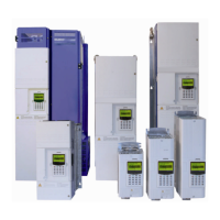
Figure A3.1: Parallel system in enclosure (Master to the left)
Master is supplied with the cable and fiber optics bundle. The user
must take out the bundle and connect it to Slave.
See bundle entry opening in the figure.
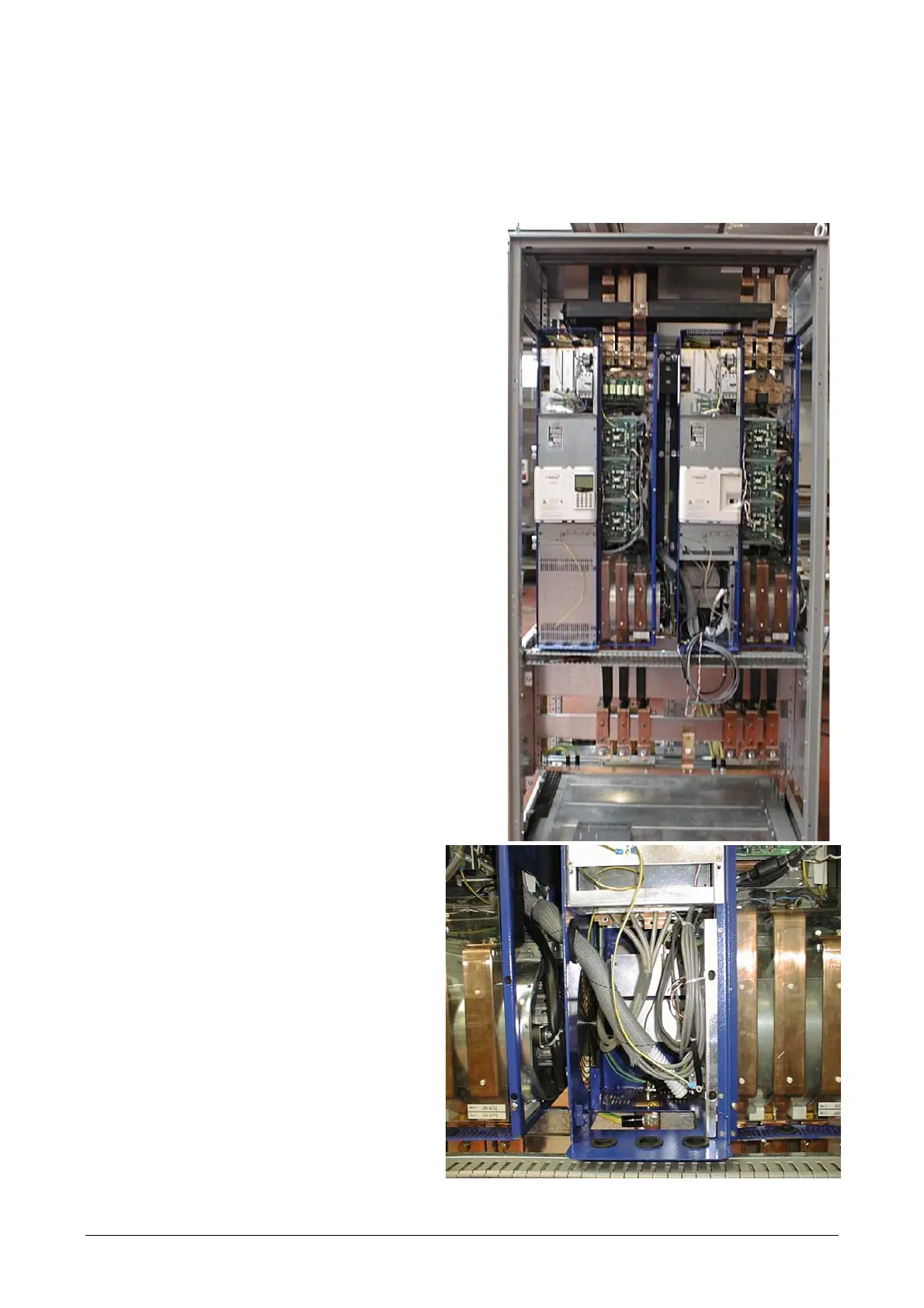
Figure A3.2: interconnection cable and fiber optics bundle