GT3000 Installation
110 IMGT30017EN
A2.4.3 Cabling
All control cables must be shielded. Control cable shielding prevents noise from entering control circuits.
The shield shall be grounded at the signal origin. Use a double-shielded twisted pair cable for analogue signals. This type of cable is recommended
for the pulse encoder signals also. Employ one individually shielded pair for each signal.
Do not use common return for different analogue signals.
A double-shielded cable is the best alternative for low-voltage digital signals but single-shielded twisted multipair cable is also usable.
A double shielded twisted A single shielded twisted
pair cable multipair cable
Run analogue and digital signals in separate, shielded cables.
Relay-controlled signals, providing their voltage does not exceed 48 V, can be run in the same cables as digital input signals. It is recommended that
the relay-controlled signals be run as twisted pairs.
Never mix 24 VDC and 115 / 230 VAC signals in the same cable.
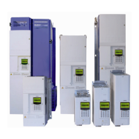
• Control signal cables must be
kept at a distance greater than
0.3m (1 foot) from power cables.
Keep both power cables and
signal cables in separate
raceways.
If it is necessary to cross power
and signal cables, cross at a 90°
(right) angle.
Figure A2.5.4.3 Cable Routing
Maximum section of control cables: 1,5mm
2
(AWG16)
A2.4.4 GROUNDING
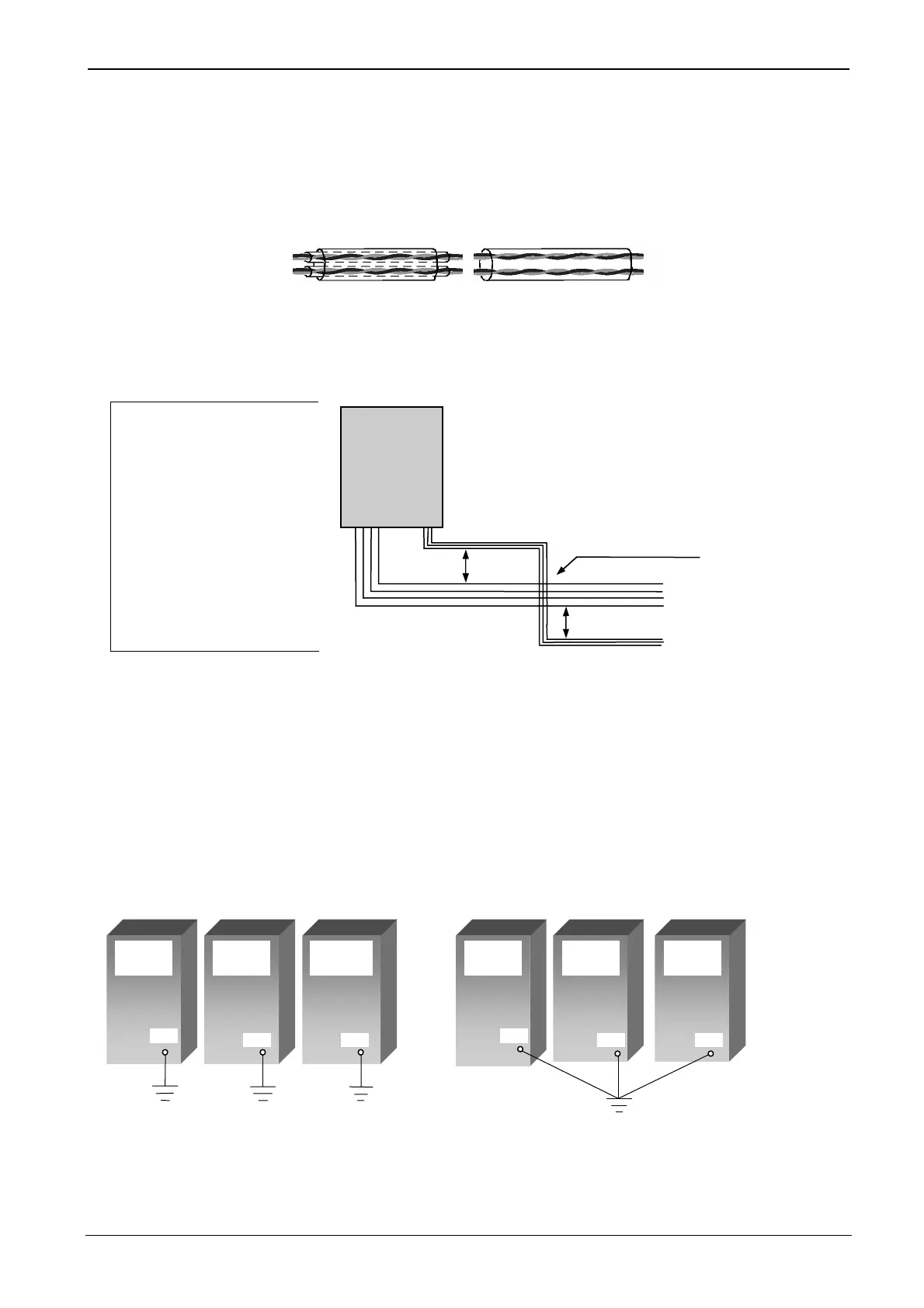
For personnel safety, proper operation and to reduce electromagnetic emission/pickup, the drive and the motor must be grounded at the installation
site. Every drive shall have its own ground. A star ground system is acceptable although it is not the preferred method.
• Conductors must be adequately sized as required by safety regulations.
• Power cable shields must be connected to the drive PE terminal in order to meet safety regulations.
• Power cable shields are suitable for use as equipment grounding conductors only when the shield conductors are adequately sized as required
by safety regulations.
• In multiple drive installations, do not connect drive terminals in series.
• The panel must have a properly sized ground bus to which all system grounds are connected. The bus bar shall be connected to plant ground.
• Ground connections must be as short as possible.
• The drive ground connection should not be shared with other devices.
• High frequency RFI requires large areas of ground bus (due to skin effect).
SVGT/2
≥0.3m
Crossing possible at 90°
≥ 0.3m
Power cables
Control cables
Drive
a) Preferred connection b) Acceptable connection
Drive Drive Drive Drive Drive