Installation GT3000
IMGT30017EN 109
Connections of the cables of the drive and motor
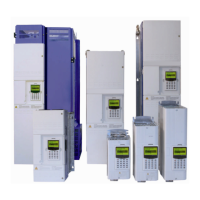
Connections Inverter - Motor with symmetrical shielded cable
a
Highlight the connection between the frame of the motor and the ground
bar of the GT3000 panel performed by means of drive-motor connection
cables (shield and PE conductors).
Drive – Motor connections with two shielded cables
Connections – converter side:
a) The PE conductors and the shields must be connected to the ground bars of the converter panel.
b) If due to the current load it is necessary to use more parallel-connected cables, the three conductors of each three-phase cable must be connected
to the phases U, V, and W.
Connections – motor side:
a) The PE conductors and the shields must be connected to the frame of the motor; therefore, on the terminal board of the motor it must be foreseen a
proper fastening plate.
b) Should it be necessary to use more parallel-connected cables, the three conductors of each three-phase cable must be connected to the phases U,
V, and W.
NOTE: Long shielded motor cables may cause external ground fault detector trips, due to leakage currents to ground and high switching frequency.
Replace the external ground fault detector with a less sensitive one or feed the drive with an isolation transformer.
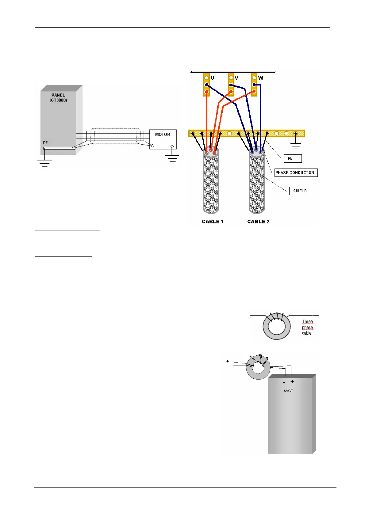
Ferrite
In the applications in which various motors are connected to one inverter and it is not possible to carry
out the complete shielding of the cables because of a shunt terminal board of the single motor (shielded)
cables, it is necessary to provide toroids in the inverter output. In order to use them correctly it is
necessary to wind the three cables (from 2 up to 5 times) within the core leaving the earth cable outside.
The part of cable from the inverter to the shunt terminal board, without braiding, shall be as short as
possible.
The SVGT0P3-166F provides an internal mono-loop ferrite ring out coming to motor.
SVGT0P3-028 feed in DC bus
In applications in which SVGT0P3-028, fed in DC bus, are used it is necessary to provide
ferrite in the drive input. For correct use, wind the two cables 2 to 3 times through the
ferrite keeping the ground cable outside.
Ferrite SAP code: ELC201767
Figure A2.5 Use of Ferrite
Grounding
The inverter panel and the motor are connected singularly to the same grounding system. The connection cables between Inverter and Motor are
grounded on both sides (both the PE conductors and the shields of these cables).