GT3000 Installation
112 IMGT30017EN
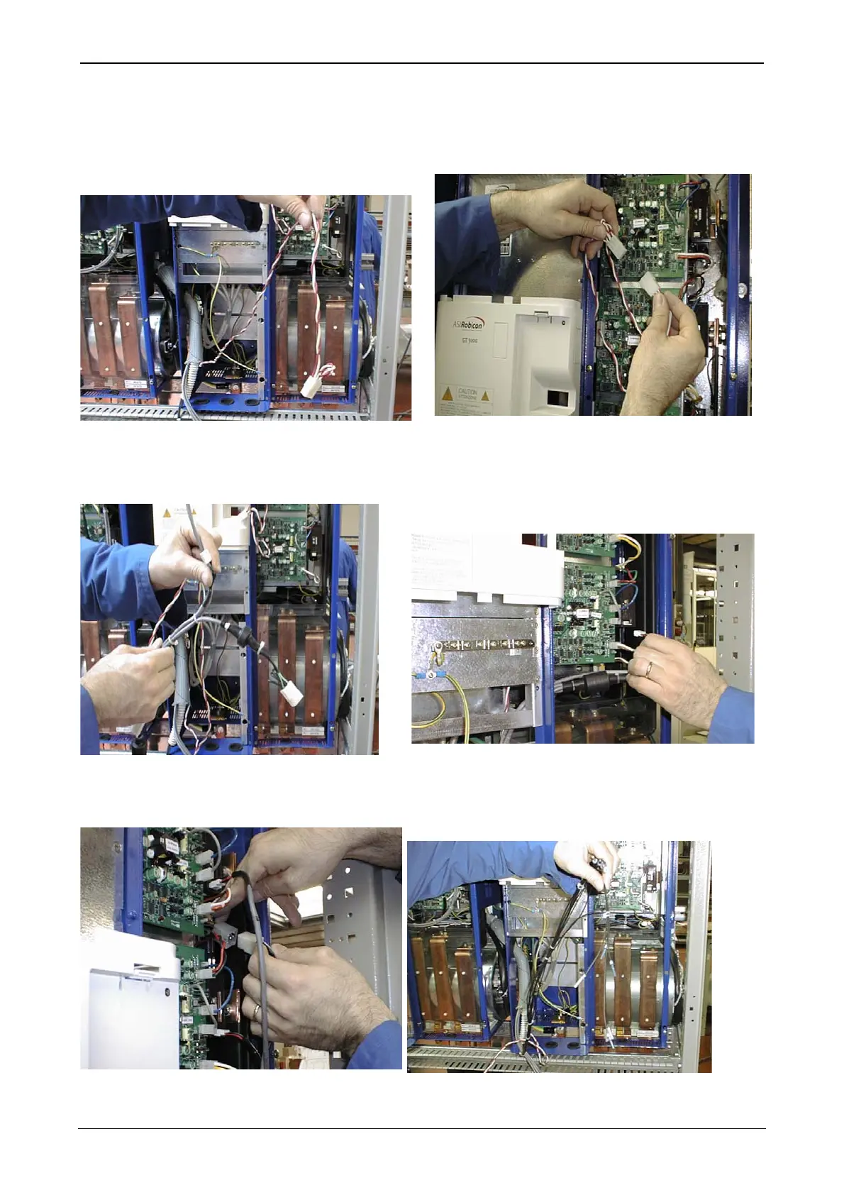
Drive boards power supply cable bundle (step 2.)
The figure shows the twisted wires and female connector for the supply
of the three SALVE drive baords.
Colors of wires can be white/red or black/blue
Figure A3.3: connector from MASTER for drive boards power supply
Male connector ON SLAVE for power distribution to the three drive
boards.
Figure A3.4 Drive boards power supply connection
TA and thermal fuse cables (steps 3. and 4.)
The cables (3) of the current transducers and the cable of the
thermal fuse are tied with straps to make connection easier.
Figure A3.5 connector for TA 1 and thermal fuse 2
The straps on cables prevent connection of cables to wrong phases of
transducers. The figure shows the instant at which TA is connected to
phase U (phase arrangement is W, V and U, up to down). TA cables bear
markings W, V and U.
Figure A3.6 connection of connectors on TA
The thermal protector male connector is located close to the phase
W drive board. Failure to connect it triggers the overtemperature
alarm.
Figure A3.7: thermal protector connector
Fiber optics bundle (step 1.)
The 9 fiber optics have different length and are marked as necessary to
give positive identification of the drive board and receiver where each of
them must be installed.
Figure A3.8: fiber optics bundle
1
2