GT3000 Braking Unit
IMGT30017EN 59
The resistance and the power of the resistor depend on the drive type, inertia of moving masses, load torque and deceleration time.
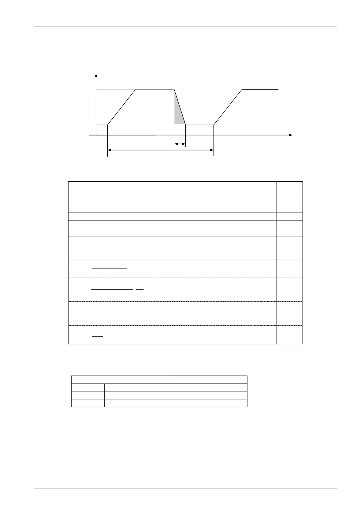
Figure 6A.2.3 gives the definitions used when a motor is braked from an initial speed N1, down to a final speed N2.
The formulas for calculating the power of the resistors are also given.
Fig. 6A.2.3
Terms and symbols used:
MB = motor braking torque from speed N1 down to N3, during time tb Nm
J = total inertia at motor shaft. Kgm
2
ML = load torque at motor shaft. Nm
PR = average resistor power. W
WB = braking energy. J
MN = Rated Torque of the motor
N2
P60
=
(Nm)
Nm
N = Rated Speed of the Motor (RPM). RPM
P = Rated Power of the Motor (W). W
V = Rated DC Voltage when braking (See values shown in table 6.1-3)
L
M
tb60
N1-N2J2π
=
B
M
In the worst case MB = 1.5 MN
Nm
1.2
1
N1
B
M0.10472
V
=
B
R
2
tb
2
N2N1
N
M-0.2
B
M0.10472
=
B
W
J
Tc
B
W
R
P
W
The ohm value of RB must be the value shown in Table 6A.2.1
Braking voltage must be selected according to the drive voltage class, as shown in the following Table
Table 6A.2.3. Braking Voltage by Drive Voltage Class
AC Voltage class of the GT3000 drive DC Voltage to be used in formula
F-Y-M 380 to 480 V 750
G 500 V 815
K-J-P 525 to 690 V 1090
After the calculations, the braking resistor can be specified using the following data:
ohmic value ()
braking energy (J)
duty cycle.
peak voltage to ground 1200 Volt.
T (s)
N (RPM)