Maintenance GT3000
IMGT30017EN 49
Input/Ouput Bridges test
The instrument suitable for that operation is a digital multimeter set to “diodes test”
Check the diodes and the IGBTs after having disconnected the power terminals to avoid false measurements due to external devices.
The first step is to do a visual test then follow the sequence shown below:
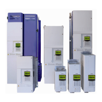
IGBTs INPUT BRIDGE
Multimeter + test prod U V W -Vc -Vc - Vc L1 L2 L3 - Vc - Vc - Vc
Multimeter – test prod +Vc +Vc +Vc U V W +Vc +Vc +Vc L1 L2 L3
Device Du Dv Dw Dx Dy Dz D1 D2 D3 D4 D5 D6
Correct value
0.25 ÷ 0.4 Vdc 0.35 ÷ 0.5 Vdc
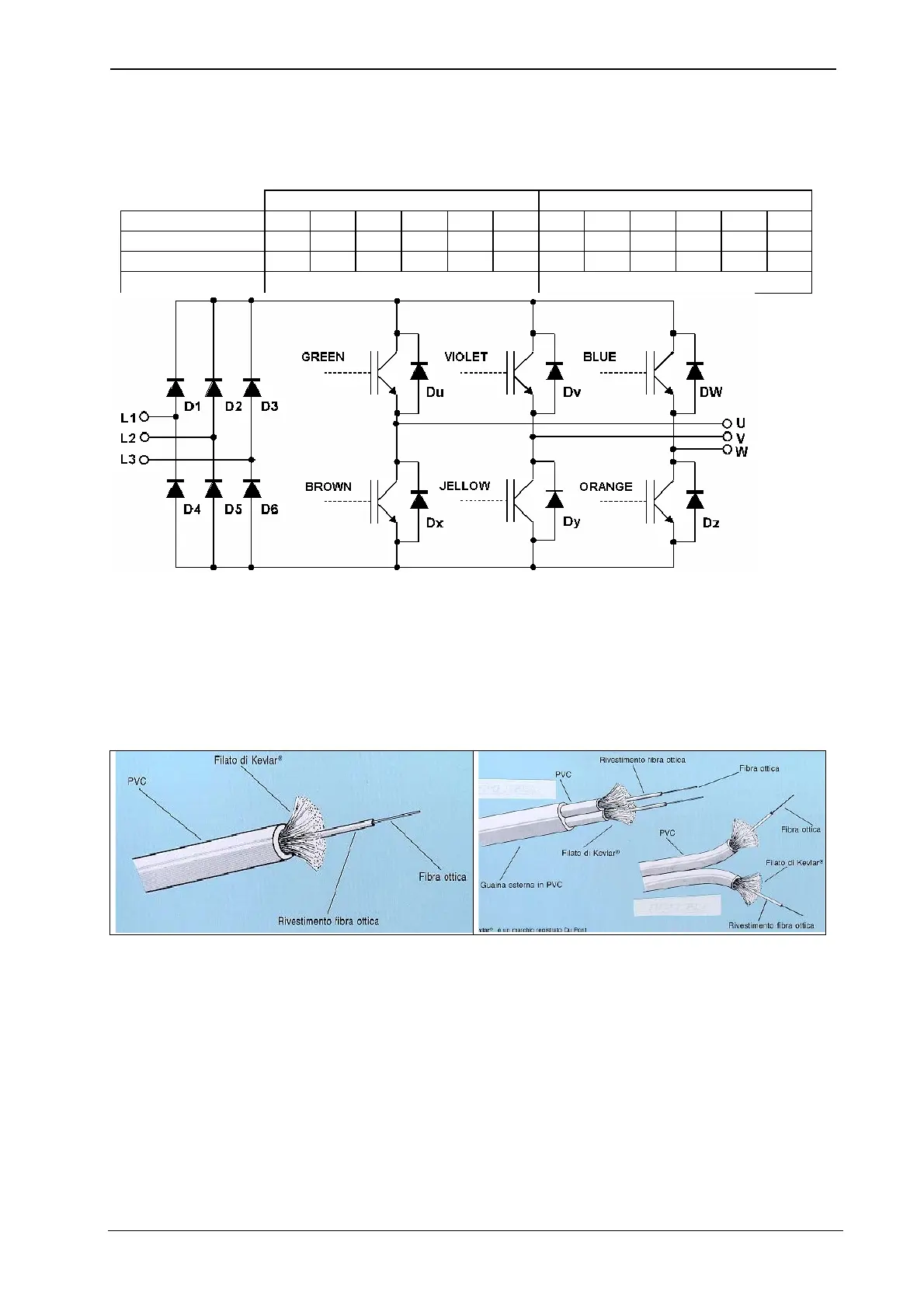
Optical fibers cable test
If there is a malfunctioning of the data transmission by optical cable, two situations are possible:
• Optical cable broken
• Malfunctioning of the data transmitter/receiver
To verify the optical cable it is necessary to do the following test:
Remove the optical cable connection and light one end by a flashlight or similar device; if the light is visible on the other end, the optical
cable is not interrupted.
NOTE the above-mentioned test may be not enough; in this case a dedicated device is necessary.