CHAPTER 4
OPERATING INSTRUCTIONS
Entire Contents Copyright 2004 by Adaptive Power Systems, Inc. (APSI) • All Rights Reserved • No reproduction without written authorization from APSI.
APS-3000P Series 4 - 6 OM-001-03000-00P-03.9
Multimeter
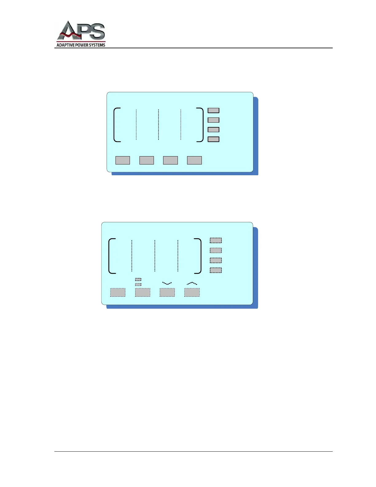
The active metering function will be indicated by the adjacent LEDs.
Press the METER button (on the MULTIMETER display) to scroll through Power (P),
Power Factor (PF), Test Time (T), Program Set (P-S) displays. For example, P2-3
means third step of the second program-set.
Press the PHASE button (on the VOLTAGE display) to scroll through phases R, S,
and T, (North American phases A, B, and C) and Σ (combined) displays. The Σ
readings are Average Line-to-Line Volts, Average Amps, Average Power Factor, and
Total Power.
Start Output
BEFORE pressing the TEST button (on the MULTIMETER display), check to ensure
every setting is correct. Press the TEST button to start the output or to start executing
AutoRUN-ON test. The TEST LED (on the FREQUENCY display) will light,
indicating normal voltage output.
M U L T I M E T E R
TEST RESET
P
PF
T
P - S
METER
/LOCAL
LOCK
V O L T A G E
PHASE
R
S
T
S
0-150
0-300