Service Support Spirit
Unique Solution WWW.ARCBRO.COM
8.2. Selection of Pattern Elements
So far, this system provides 24 pattern elements, which is expandable at any time as per
client requirement. It is allowed to select the interested pattern by pressing [↑], [↓], [←] and/or
[→] key to move the cursor to right position and press [ENTER] to acknowledge the selection.
Note: The 17th pattern element is customized element.
8.3. Arrangement and Layout of Pattern Element
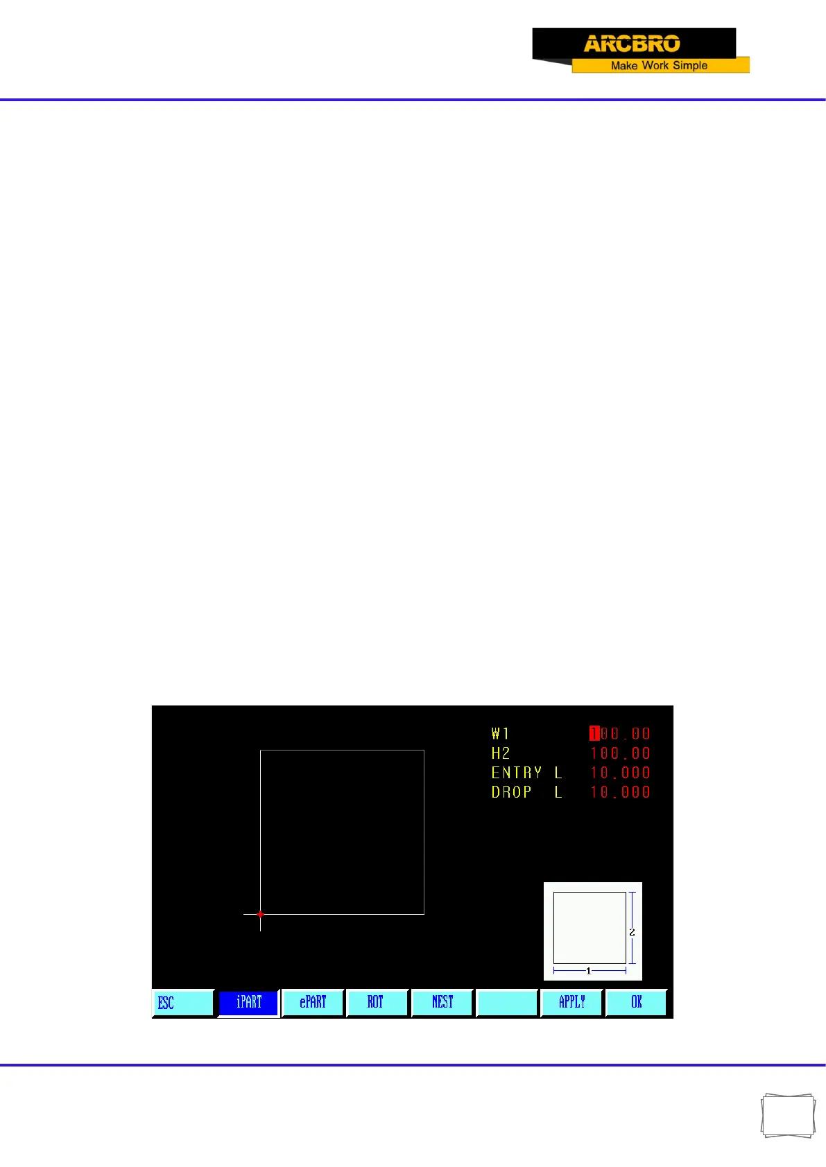
After pattern element is selected as per the above-mentioned procedure, the system will prompt
at the upper right corner to input parameters for the pattern, as show in Fig. 8.2
【F1】IPART Workpiece: To machine into workpiece that is solid internally.
【F2】ePART Hole: To machine into hole that is solid externally.
【F3】ROT Rotate: The system will prompt to input rotation angle and press [ENTER] or [F6]
to acknowledge. The pattern rotated such an angle will appear. Counterclockwise direction is
taken as positive angle.
【F4】NEST : The system will prompt user to provide:
ROWS----Row number of machined parts array
COLUMNS ----Column number of machined parts array
H-BETWEE ----Distance between rows.
W-BETWEE----Horizontal distance between machined parts
OFFSET----The deviation of raw misplacement, as shown in Fig. 8.3.
Fig. 8.2 Pattern setting menu