7.5 Product Topology
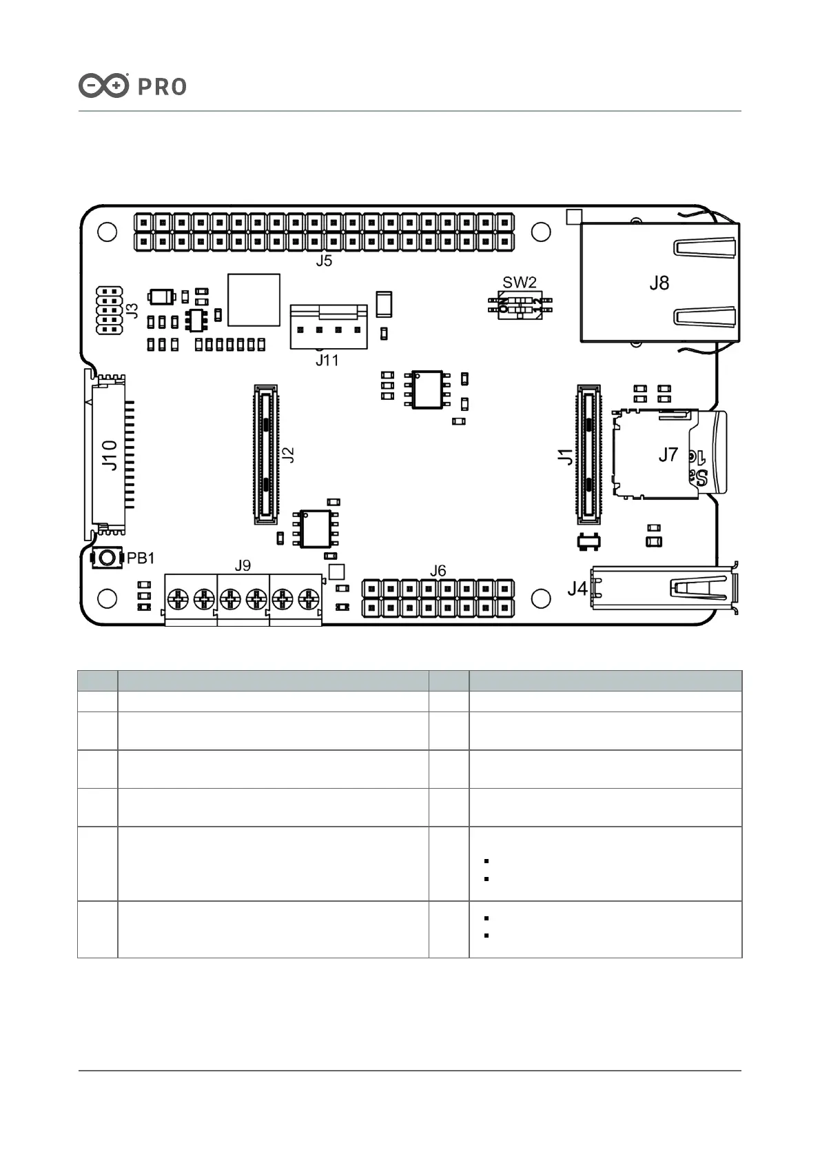
An overview of the Portenta Hat Carrier topology is illustrated in Figure 5.
Figure 5. Portenta Hat Carrier topology
Item Feature Item Feature
J1, J2 High-Density connectors for Portenta boards J8 RJ45 connector for Ethernet
J3 JTAG male connector for debugging J9
Screw terminal for power supply and CAN
bus
J4
USB-A female connector for data logging and
external devices
J10
MIPI camera connector (only for Portenta X8
board)
J5
40-pin male header compatible with Raspberry Pi®
Hats
J11 Male header for external fan
J6 16-pin male header for analog and digital pins SW2
DIP switch (2 positions):
Ethernet mode
Reserved for future applications
J7 MicroSD slot for data logging and media purposes PB1
Simple press: Programmable button
Long press: Flashing mode
Table 14: Product Topology Description

 Loading...


