7.5.8 Screw Terminal Block (J9)
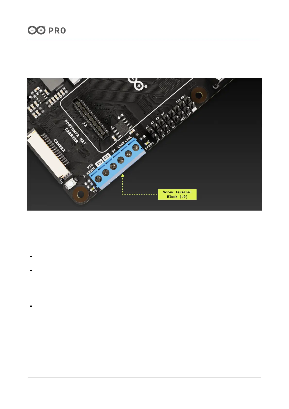
The screw terminal block connector shown in Figure 12 contains the power supply and CAN bus communication
pins.
Figure 12. Screw terminal block connector of the Portenta Hat Carrier
Power Pins
The Portenta Hat Carrier and any connected board to it can be powered using the power terminals located on the
screw terminal block (J9):
VIN 7-32VDC and GND terminals: Supply the board using a voltage range of +7-32 VDC. This method is
particularly convenient when powering the board with batteries.
5V and GND terminals: Power the board with a fixed voltage of +5 VDC. Additionally, these pins can power
external peripherals operating at +5 VDC. An AP63200WU-7 buck converter (U7) steps down the input voltage
from +7-32 VDC to the +5 VDC used by the carrier and the connected board to it.
CAN Bus Pins
CANH and CANL terminals: The Portenta Hat Carrier has a high-speed CAN transceiver based on the
TJA1049T/3J IC. These terminals enable reliable CAN bus communication. The 120 ohms termination resistor is
not included in the device so make sure to add it in your final deployment to meet the bus requirements and
obtain the ideal performance.

 Loading...


