5 Features
5.1 General Specifications Overview
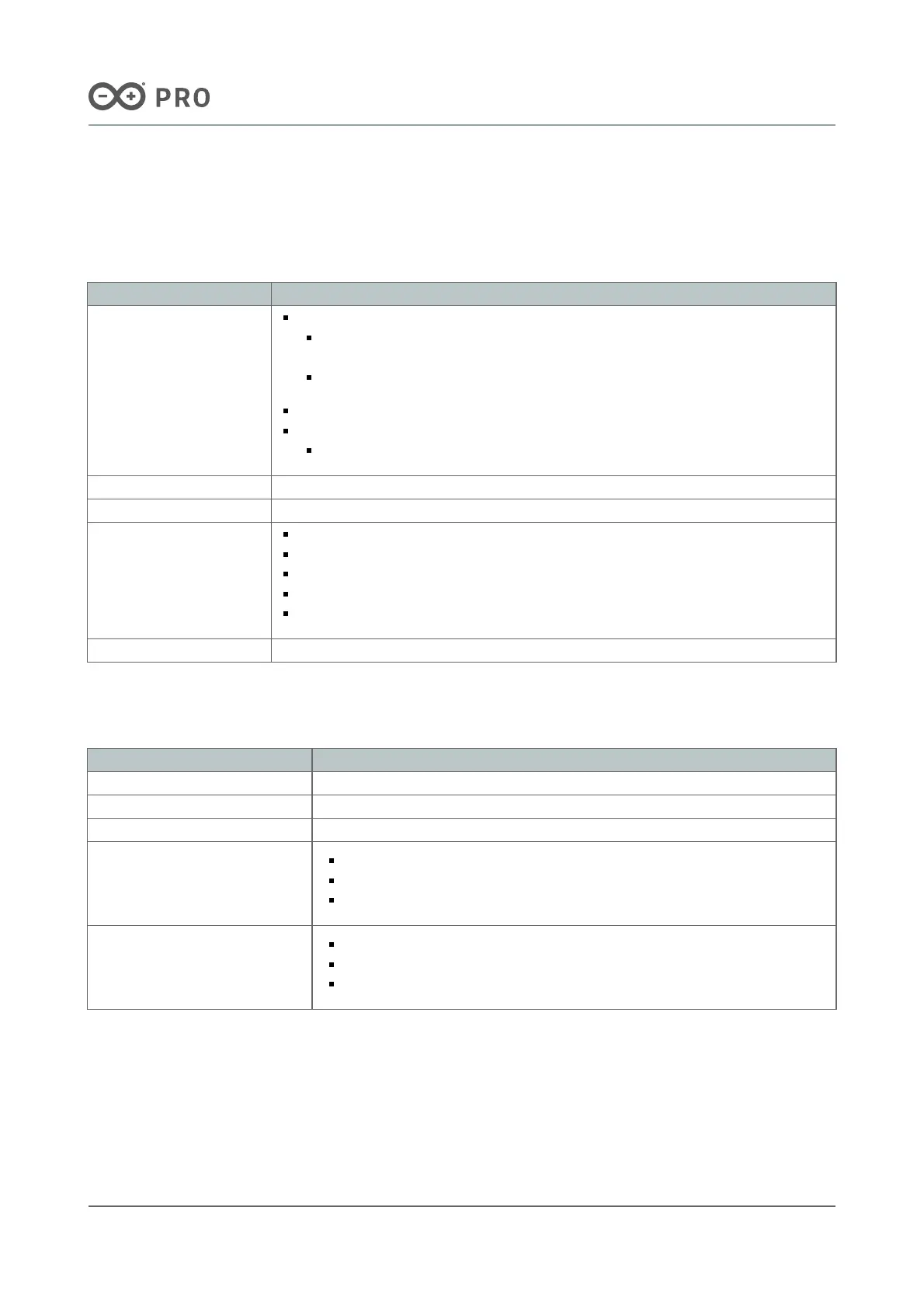
Characteristics Details
Supply voltage
From the onboard screw terminal block (J9):
+7-32 VDC to power both the carrier and the connected Portenta family
board
+5 VDC power supply
+5 VDC from the USB-C® connector of the connected Portenta family board
From the onboard 40-pin header connector (J5):
+5 VDC power supply
Carrier maximum current 1.5 A
USB connectivity USB-A for data logging and external peripherals (x1)
Communication
interfaces
Ethernet (x1)
SPI (x1)
I2S (x1)
I2C (x3)
UART (without flow control) (x3)
Certifications CE/RED, FCC, UKCA, IC, RoHS, REACH and WEEE
Table 1: General specification overview of the Portenta Hat Carrier
5.2 Communication Interfaces
Interfaces Connector
Ethernet (x1) RJ45 connector (J8)
SPI (x1) 40-pin header connector (J5)
I2S (x1) 40-pin header connector (J5)
I2C (x3)
I2C0: 40-pin header connector (J5)
I2C1: High-Density connector (J1)*
I2C2: 40-pin header connector (J5)
UART (without flow control) (x3)
UART1: 40-pin header connector (J5)
UART2: 16-pin header connector (J6)
UART3: 40-pin header connector (J5)
Table 2: Communication interfaces of the Portenta Hat Carrier
*Note: I2C1 is shared also with the onboard EEPROM memory and the MIPI connector.

 Loading...


