Chapter 2: Overview of the Argus TubeSpec System
20 NOV CTES Argus TubeSpec User Guide
included in the oiler module to prevent the sponge from compressing on the top side of the pipe. Said com-
pression would prevent sponge contact with the bottom side of the pipe.
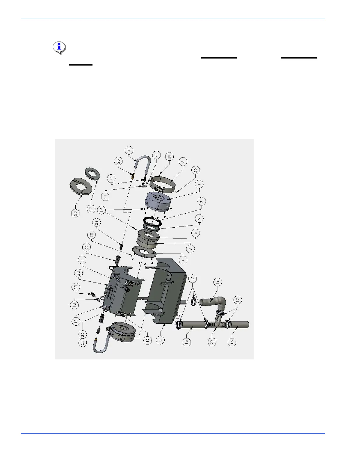
Numbers correspond to those found in the figure entitled Oiler Assembly, below, and in the Parts for Oiler
Assembly section.
Oil is pumped into the sponge at low pressure through a hose that is connected to the top cover (number 9)
from the quick-disconnect coupler and nipple (numbers 22 and 23). A tab is welded to the top cover to sup-
port the connection point where the oil lines from the lube tank are connected.
The top and bottom covers (numbers 9 and 8) are designed to keep the oilers in place, and to keep liquid
and solid debris from contaminating the environment. The bottom cover uses a 1.5" clear, PVC tube (num-
ber 16) to direct the waste back to the lube tank, where it is filtered and recycled.
Oiler Assembly