installation &
operating instructions
Design Envelope 4322 & 4372
Tango Pumping Unit
19
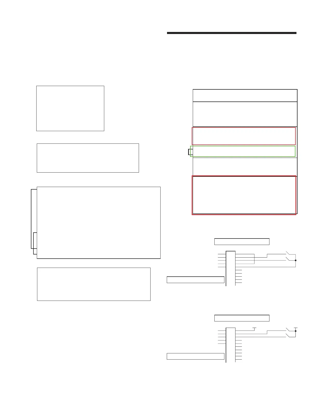
2.3.4.3 control terminal wiring for depm2 motors
fig 2.3.2.c Motor Control Board
2.3.5 analog / digital inputs
2.3.5.1 analog / digital inputs for frame 71 motors
i wiring digital inputs for frame 71 motors
Recommended, internal npn is default factory setting
Optional, external power supply NPN
internal power supply npn
internal input impedance 10kOhm
common dig input 1-2
dig input 2
dig input 1
+24Vdc
gnd
j1
10
9
8
7
6
5
4
3
2
1
external power supply npn
internal input impedance 10kOhm
common dig input 1-2
dig input 2
dig input 1
+24Vdc
gnd
j1
10
9
8
7
6
5
4
3
2
1
0
+24V
MODBUS CONNECTOR (J15)
Pin 1 485-A
Pin 2 485-B
Pin 3GND ISOLATED
RELAYS CONNECTOR (J12)
Pin 1Relay 1 NO
Pin 2Relay 1 COM
Pin 3Relay 1 NC
Pin 4Relay 2 NO
Pin 5Relay 2 COM
Pin 6Relay 2 NC
I/O CONNECTOR (J16-J18)
Pin 1+24 ISOLATED OUTPUT (200mA)
Pin 2GND ISOLATED
Pin 3+10V ISOLATED / Analog Output 4-20mA (+)
Pin 4Analog Output 4-20mA (-)
Pin 5Analog Output 0-10V
Pin 6GND ISOLATED
Pin 7+24 ISOLATED
Pin 8Digital Input 1
Pin 9Digital Input 2
Pin 10 Comm NPN / PNP (jumper)
Pin 11 GND ISOLATED
Pin 12 Digital Output 1 (open collector 20mA)
Pin 13 +24 ISOLATED
Pin 14 Digital Output 2 (open collector 20mA)
Pin 15 Analog Input 1, 4-20mA (+)
Pin 16 Analog Input 1, 0-10V
Pin 17 +10V ISOLATED
Pin 18 GND ISOLATED
Pin 19 Analog Input 2, 4-20mA (+)
Pin 20 Analog Input 2, 0-10V
Digital
Input
Wiring
Analog
Input
Wiring
MODBUS CONNECTOR (2x RJ-45 - Female Ports, Interchangeable)
Pin 1 NOT USED
Pin 2 NOT USED
Pin 30 VOLT
Pin 4 NOT USED
Pin 5 NOT USED
Pin 6+24 VOLT
Pin 7 RS 485- Modbus RTU
Pin 8 RS 485+ Modbus RTU
RELAYS CONNECTOR
RELAY EXPANSION CARD (Optional Accessory)
Pin 14 RL1 - COM Auxiliary Relay Output 1 Common
Auxiliary Relay Output 1 Normally Open
Auxiliary Relay Output 1 Normally Closed
Auxiliary Relay Output 2
Auxiliary Relay Output 2
Pin 15 RL1 - NO
Pin 16 RL1 - NC
Pin 17 RL2 - A
Pin 18 RL2 - B
I/O CONNECTOR
Pin 1
Pin 2
Pin 3
Pin 4
Pin 5
Pin 6
Pin 1
Pin 2
Pin 3
Pin 4
Pin 5
Pin 6
Pin 7
Pin 8
Pin 9
Pin 10
Pin 11
Pin 12
Pin 13
+24V DC 24 Volt DC Output (100mA)
DI 1
Digital Input 1: 8-30V DC = High (30V DC Max)
DI 2
Digital Input 2: 8-30V DC = High (30V DC Max)
Not Used
+10V DC +10 Volt DC Output (10mA)
AI 1Programmable Analog Input 1 (0-10V / 0-20mA)
0V / COM0 Volt Common for AI/AO/DI/DO
AO Analog Output: 4 - 20mA (20mA Max.)
0V / COM0 Volt Common for AI/AO/DI/DO
AI 2Programmable Analog Input 2 (0-10V / 0-20mA)
DO Digital Output: 24 Volt DC (20mA Max.) when Active.
STO+ STO + 24V DC Connection (Run Permit).
STO- STO 0 Volt Connection (Run Permit).
RL3 - A
RL3 - B
Auxiliary Rela
y Output 3
Auxiliary Relay Output 3
RL4 - AAuxiliary Relay Output 4
RL4 - BAuxiliary Relay Output 4
RL5 - AAuxiliary Relay Output 5
RL5 - BAuxiliary Relay Output 5


 To Next Page