DrillSaw Highspeed 200™ User’s Guide
DFU-0225-2 Rev. 0 Page 13 of 58
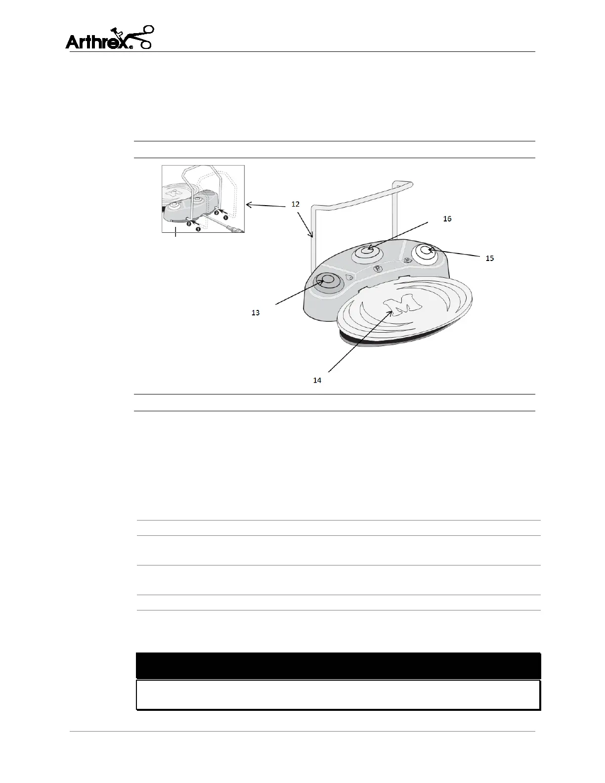
2.5.4 Foot Control Unit (S-N1)
Figure 4 uses a numeral callout system to identify the main elements on the foot
pedal unit, which are listed and labeled in Table 4. These callouts are referenced
throughout this User’s Guide.
Figure 4 Foot Control Unit (S-N1)
Table 4 Foot Control Unit Elements (S-N1)
Handle for Foot Control Unit:
– Attach:
(1) Guide the ends of the Handle into the two holes of the Foot
Control Unit.
(2) Insert the Handle until the stop is reached.
- Detach:
Pull out the handle until completely removed.
Grey – Start motor (pedal), variable or ON/OFF,
factory setting = variable
Yellow – Change motor direction, clockwise / counterclockwise
rotation
Orange – Change program, programs 1 to 6
When counterclockwise rotation is used, the motor panel emits a warning tone
before the motor starts (after approximately 1 second).
WARNING!
The ESD (electrostatic discharge) spring contact on the underside of the foot
control must touch the floor during operation.
 Loading...