Page 37
Output Programming
There are (8) programmable outputs, 24V DC, and 0V DC supply available through the output connector on the bottom
of the controller. See the chart at the end of this section for pin location and other technical information. All the
outputs can be set up with the following instructions from the ‘Run Tool’ Screen:
• Tap the ‘Setup’ Button
o Make sure the task shown at the top is the one to be programmed.
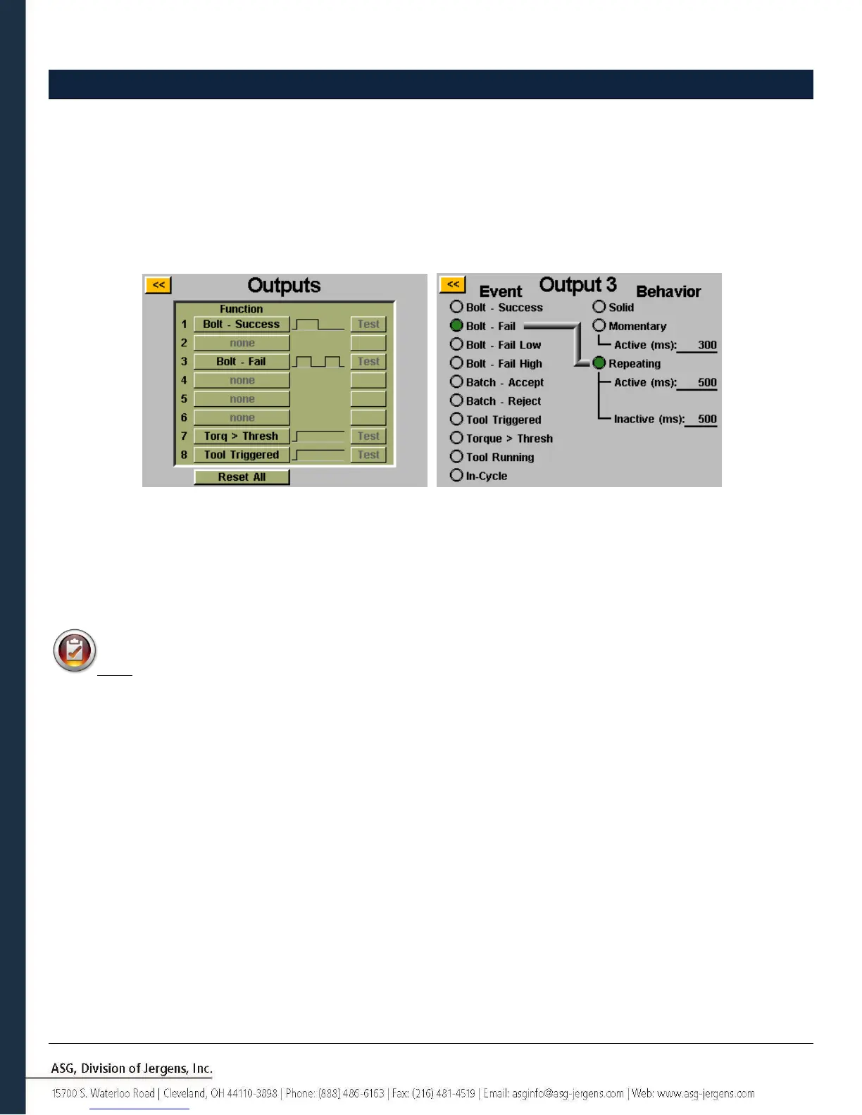
• Tap the ‘Outputs’ Button
Select an available output button by tapping the ‘none’ button. Under the ‘Event’ heading, select the appropriate radio
button. Select the type of output you would like under the ‘Behavior’ heading, and if necessary input the time intervals
for the non-solid outputs. To adjust these values, tap on the number, enter the value you wish on the on-screen keypad,
then tap the enter button. Any un-saved changes will appear in red until they are saved by exiting the screen with the
yellow [<<] button.
Note: Back on the ‘Outputs’ screen, you will have the opportunity to test the output signal to your device by
tapping the ‘Test’ button next to each output.