ADR141A /
ADR241A
Ref ID : ADR241A/IM/I&P
Rev No. : 02
Page No. : 36 of 150
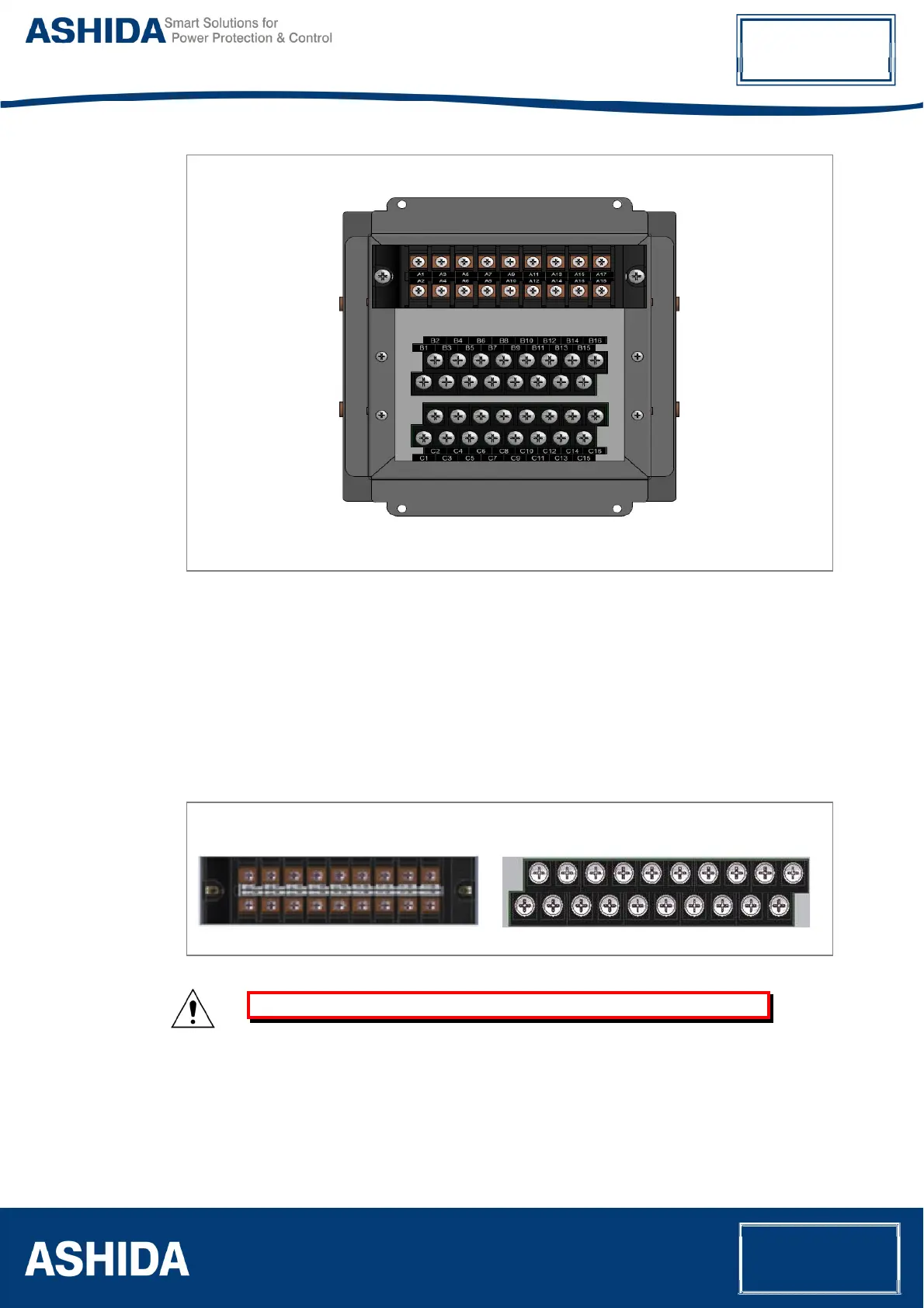
Figure 5: Rear view-Terminal Connection of ADR141A/ ADR241A
CT/Auxiliary power/Input/Output connections
The use terminal blocks used for ADR141A/ ADR241A devices are as shown below.
The terminal block of ADR141A/ ADR241A consists of up to 50 x M4 screw terminals. M4
terminal blocks are used for CT/ auxiliary power/ input/ output connections. The wires should
be terminated with rings using 90° ring terminals, with no more than two rings per terminal.
The product is supplied with sufficient M4 screws for proper connection.
M4 I/O Terminal blockM4 CT Terminal block
Figure 6: Terminal blocks
Caution: Always fit an insulating sleeve over the ring terminal.
Rear Serial Port connection (for ADR241A)
The rear serial port is intended for use with a permanently wired connection to a remote
SCADA system. The physical connectivity is achieved using this terminal for signal
connection. The terminal block is located at the rear of the relay as shown below.