ADR141A /
ADR241A
Ref ID : ADR241A/IM/UG
Rev No. : 02
8 USER GUIDE
5
1
2
3
4
6
7
8 9 10
12
11
5
1
2
3
4
6
7
8 9 10
12
11
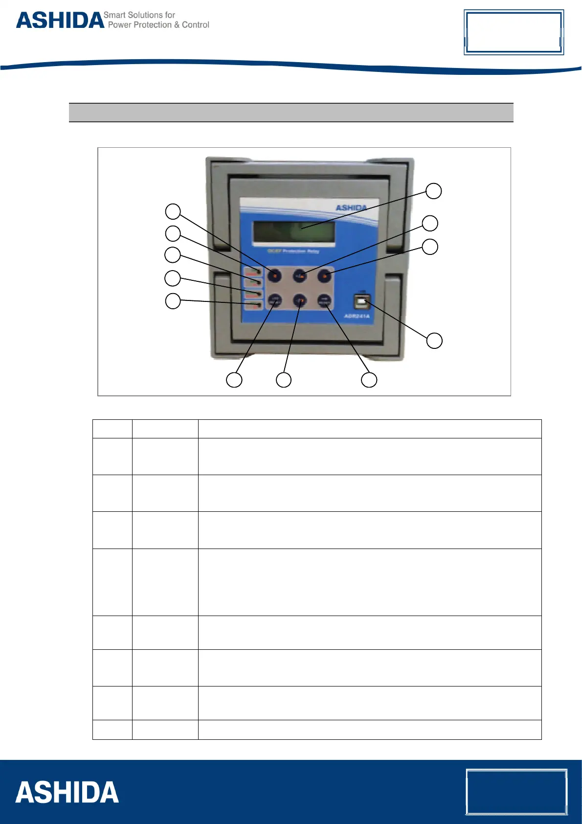
No Legend Function
1.
ON / ERROR : Green LED indicates Relay OK.
: Red LED indicates problem in Relay hardware.
2.
PKP / HF : Green LED indicates Pick-up
: Red LED indicates relay operated at HF.
3.
OC FAULT /
EF FAULT
: Green LED indicates the relay tripped by OC. Hand Reset (HR) Type.
: Red LED indicates the relay tripped by EF. Hand Reset (HR) Type.
4.
TRIP / BF : Green LED Indicates that Trip pulse is being executed. SR type when TRIP contact
selected as SR and HR type when TRIP contact selected as HR.
: Red LED indicates BF operated. SR type when BF contact selected as SR and HR
type when BF contact selected as HR.
5.
◄ : Feather Touch Key Left arrow Key [
◄] for navigating through the menus
and submenus and save settings.
6.
+ /▲ : Feather Touch Key [ + ] Plus to INCREMENT the values &
[▲] to SCROLL the Main Menu up.
7.
► : Feather Touch Key [►] to VIEW the settings and to navigate through the menus
and submenus.
8.
LED RESET : Feather Touch Key LED RESET to Reset LED and HR Type Output contact