NUMERICAL OC/EF PROTECTION RELAY ADR141C/241C
ASHIDA Electronics Pvt. Ltd.
Ref: Manual / ADR141C / 241C
Issue: 04D
Date : 10.07.2014
Page 13/86
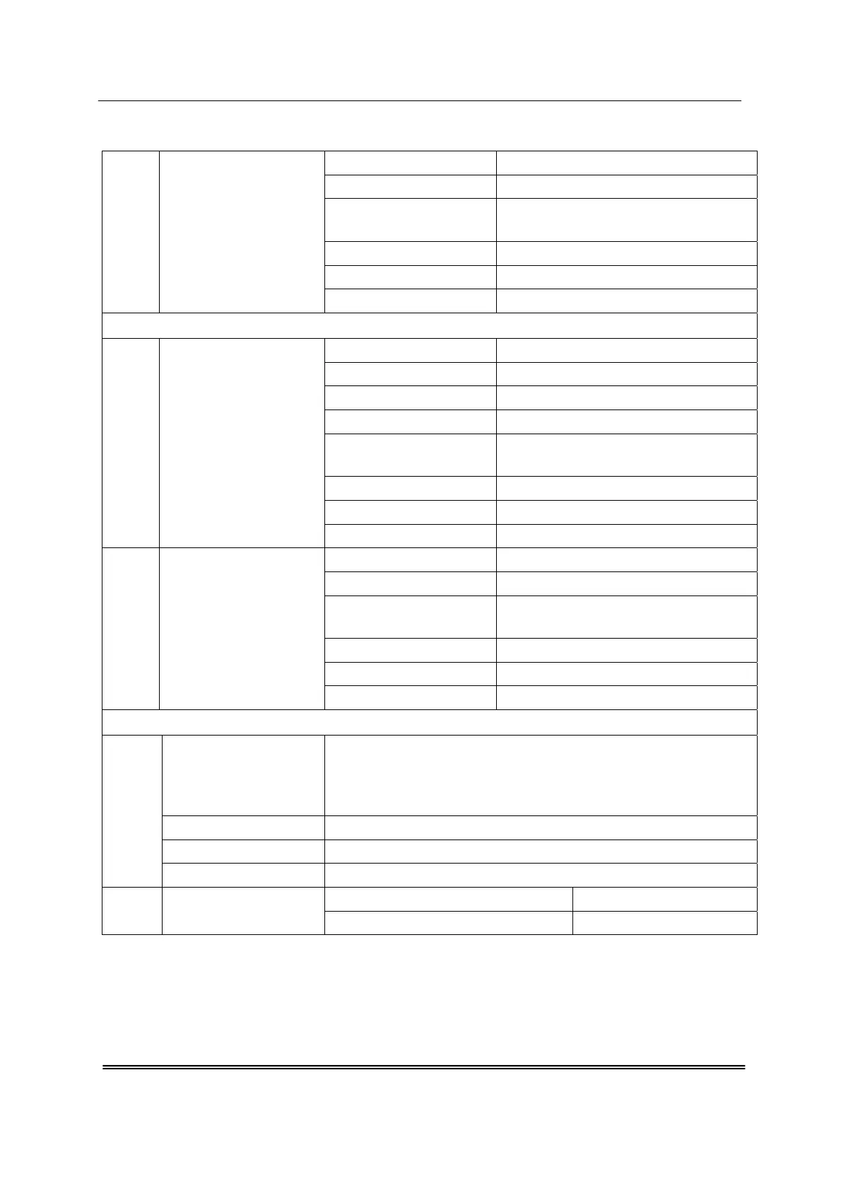
XV. Earth Fault Section (3Io) : 3Io> Settings 10% – 250% in steps of 1%
: 3Io> Time Multiplier (TMS) x0.01 – x1.00 in step of 0.01.
: IE> Curve
(Operating Time)
C1 – C6
( IDMT curve C1 – C5 or Definite Time C6 )
: 3Io> C6 Delay 0.1– 99.9 Sec in steps of 0.1Sec.
: 3Io>> Settings 50% – 3000% in steps of 50%
: 3Io>> Delay 0 – 2.00 Sec in steps of 0.01Sec.
Cold Load settings
XVI. Phase Section (Ip) : CL Enable 01: YES, 02: NO
: CL Timer 0.01 - 2.00S in steps of 0.01 sec
: IP> Settings 10% – 250% in steps of 1%.
: IP> Time Multiplier (TMS) x0.01 – x1.00 in steps of 0.01
: IP> Curve
(Operating Time)
C1 – C6
( IDMT curve C1 – C5 or Definite Time C6 )
: IP> C6 Delay 0.1 – 99.9 Sec in steps of 0.1Sec.
: IP>> Settings 50% – 3000% in steps of 50%
: IP>> Delay 0 – 2.00 Sec in steps of 0.01Sec.
XVII. Earth Fault Section (3Io) : 3Io> Settings 10% – 250% in steps of 1%
: 3Io> Time Multiplier (TMS) x0.01 – x1.00 in step of 0.01.
: IE> Curve
(Operating Time)
C1 – C6
( IDMT curve C1 – C5 or Definite Time C6 )
: 3Io> C6 Delay 0.1 – 99.9 Sec in steps of 0.1Sec.
: 3Io>> Settings 50% – 3000% in steps of 50%
: 3Io>> Delay 0 – 2.00 Sec in steps of 0.01Sec.
Operational Indicators (Flags) 4 user assignable bi-colour output LED Default assignment
XVIII.
LED1 - PROT.H /ON : Green LED indicates Relay OK (Protection Healthy)
: Red LED indicates Fault in following conditions.
1. Problem in relay Hardware.
2. Trip Circuit Fault
LED 2 - PICK-UP : Red LED indicate Start of timer Self Reset (SR) Type
LED 3 - FAULT : Red LED indicate Relay Operated Flag (HR)
LED 4 - TRIP : Green LED indicates Output TRIP relay contact closer (SR) Type
XIX.
Drawing References
: For Typical External connection - ADV02702
: For Cabinet Type - MAC01501 (CSF)