NUMERICAL OC/EF PROTECTION RELAY ADR141C/241C
ASHIDA Electronics Pvt. Ltd.
Ref: Manual / ADR141C / 241C
Issue: 04D
Date : 10.07.2014
Page 70/86
RS485 is the most versatile communication standard in the standard series defined by the
EIA, and widely used for communication interface in data acquisition and control applications
where multiple nodes communicate with each other.
RS485 functionality
1. Connect DTE's (Data Terminal Equipment) directly without the need of modems.
2. Connect several DTE's in a network structure.
3. Ability to communicate over longer distances.
4. Ability to communicate at faster communication rates.
5. There is error detection implemented in the higher level protocol to detect the data
corruption and resend the information at a later time.
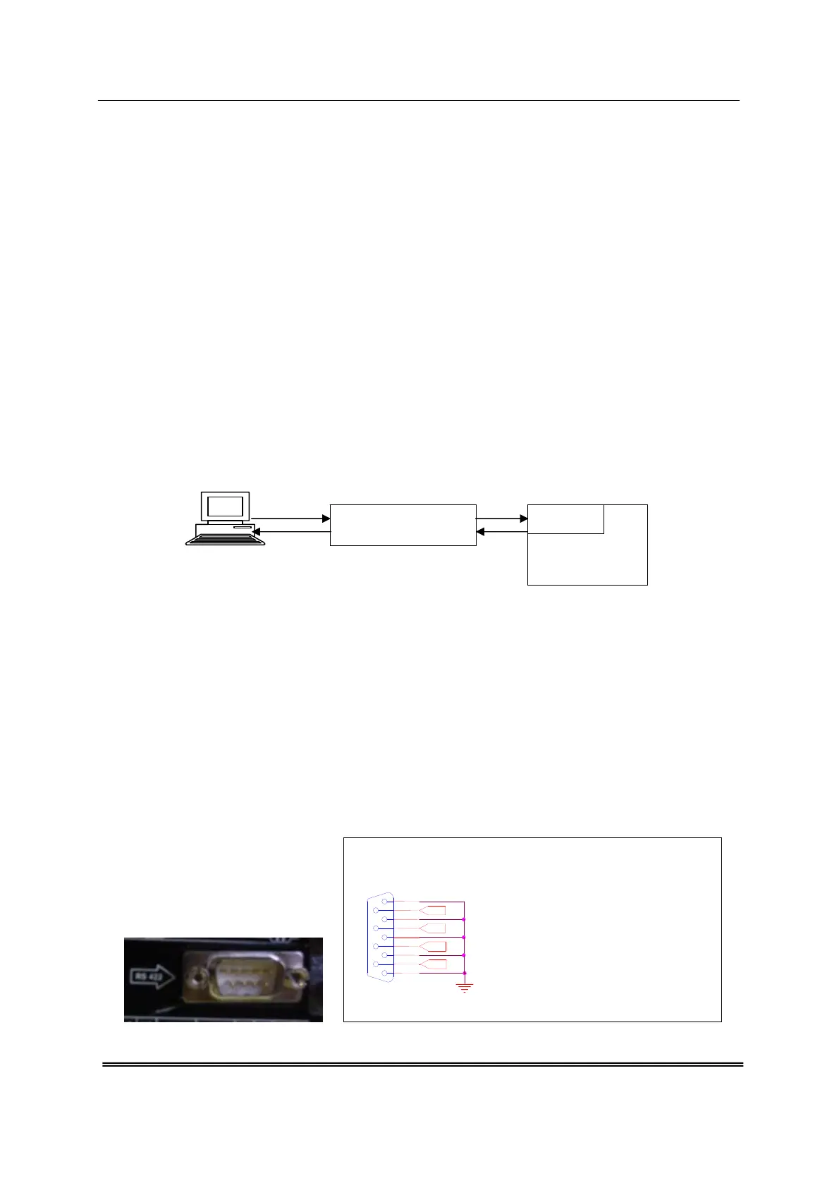
10.3. Physical connection and link layer
Connection is available for IEC60870-5-103 through the rear RS485 port. For this
communication Isolated RS232 to RS485 Convertor is used.
1
2
Fig. 10.1 Block Diagram of communication link
1. PC to RS232 Port of convertor and convertor to RS485 of Relay.
2. RS485 to convertor and back to PC.
The parameters of the communication are the following:
• None (NO) Parity, Odd Parity & Even Parity
• 8 Data bits
• 1 stop bit
• Data rate 1200, 2400, 9600, 19200 38400 or 57600 bauds
RS485 communication port Electrical Connection provided at back of Relay
Fig. 10.2
RS485 PORT
D9 Male
5
9
4
8
3
7
2
6
1
RX -
RX +
TX +
TX -
Rx+ and Rx- are Input to relay
Tx+ and Tx- are output from relay
RS232 to RS485
ISOLATED CONVERTOR
ADR 241C
RELAY
RS485