NUMERICAL OC/EF PROTECTION RELAY ADR141C/241C
ASHIDA Electronics Pvt. Ltd.
Ref: Manual / ADR141C / 241C
Issue: 04D
Date : 10.07.2014
Page 43/86
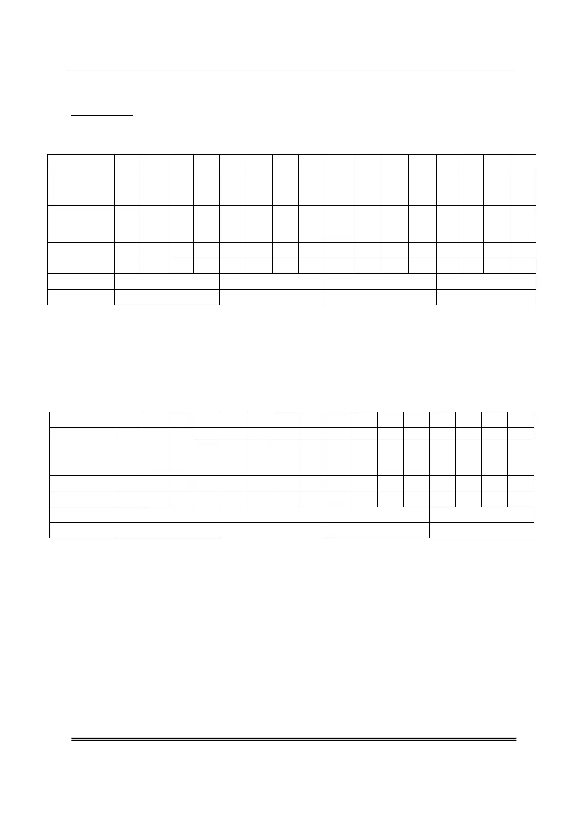
For Example:
1. If you want to set Led L2 Green for Inst. Fault flag (HR), then you set bit as follow.
i.e. L2 Green A = 00F0
L2 Green B = 0200
2. If you want to set Relay 4 for BF (SR), then you set bit as follow.
i.e. RL2 A = 0200
RL2 B = 0000
Bit Posit. 15 14 13 12 11 10 9 8 7 6 5 4 3 2 1 0
A
3Io
>>
Trip
B
>>
Trip
Y
>>
Trip
R
>>
Trip
B
SR
/
HR
Bit for A
0 0 0 0 0 0 0 0
1 1 1 1
0 0 0 0
Bit for B
0 0 0 0
0 0 1 0
0 0 0 0 0 0 0 0
L2 Green A 0 0 F 0
L2 Green B 0 2 0 0
Bit Posit. 15 14 13 12 11 10 9 8 7 6 5 4 3 2 1 0
A BF
B
SR
/
HR
Bit for A
0 0 0 0
0 0 1 0
0 0 0 0 0 0 0 0
Bit for B
0 0 0 0
0 0 0 0
0 0 0 0 0 0 0 0
L2 Green A 0 2 0 0
L2 Green B 0 0 0 0