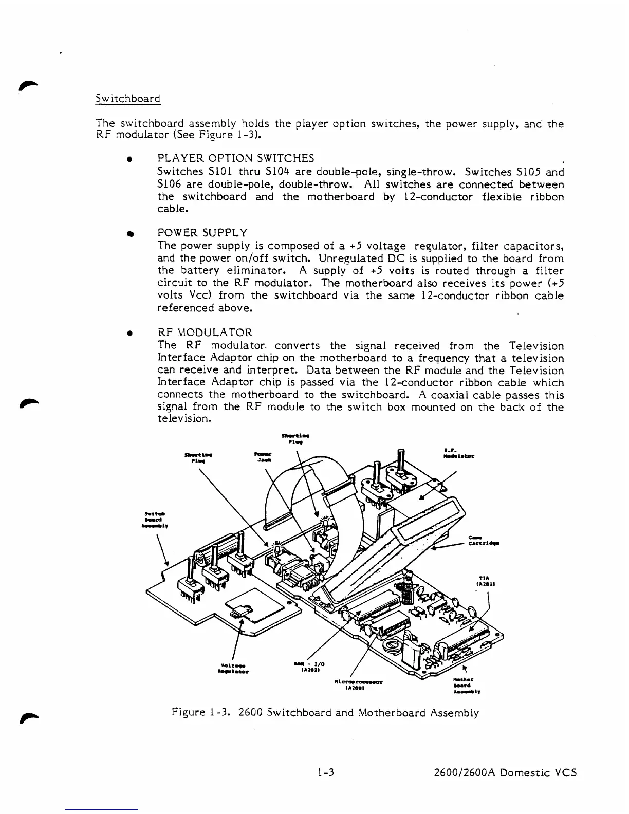
Switchboard
The
switchboard assembly holds the player option switches, the power supply,
and
the
RF
modulator (See Figure 1-3).
0
PLAYER
OPTION SWITCHES
Switches SlOL thru SL04 are double-pole, single-throw. Switches SL05 and
5106
are double-pole, double-throw.
All switches are connected between
the switchboard and the motherboard
by
1
2-conductor flexible ribbon
cable.
POWER
SUPPLY
The power supply is composed of
a
+5
voltage regulator, filter capacitors,
and the power on/off switch. Unregulated
DC
is supplied to the board from
the battery eliminator.
A
supply
of
+5
volts
is
routed through
a
filter
circuit to the RF modulator. The motherboard also receives its power
(+5
volts
Vcc)
from the switchboard via the same 12-conductor ribbon cable
referenced above.
0
RF
MODULATOR
The RF modulator. converts the signal received from the Television
Interface Adaptor chip on the motherboard to
a
frequency that
a
television
can receive and interpret.
Data between the RF module and the Television
Interface Adaptor chip is passed via the 12-conductor ribbon cable which
connects the motherboard to the switchboard.
A
coaxial cable passes this
siqnal from the
RF
module
to
the switch box mounted on the bac!c of the
television.
Ilarq-
v
mchm
(Amml
mrd
hm.r.1~
Figure
1-3.
2600
Switchboard and Motherboard Assembly
1-3 2600/2600A Domestic
VCS