Consumer Product Service
Manager
ofa
Tehnical Support
TECH
TIP
number
4.
-
--
---
-
-- -
-
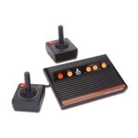
MODEL:
OOA
DATE:
1
/17/87
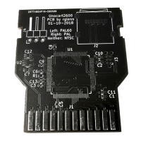
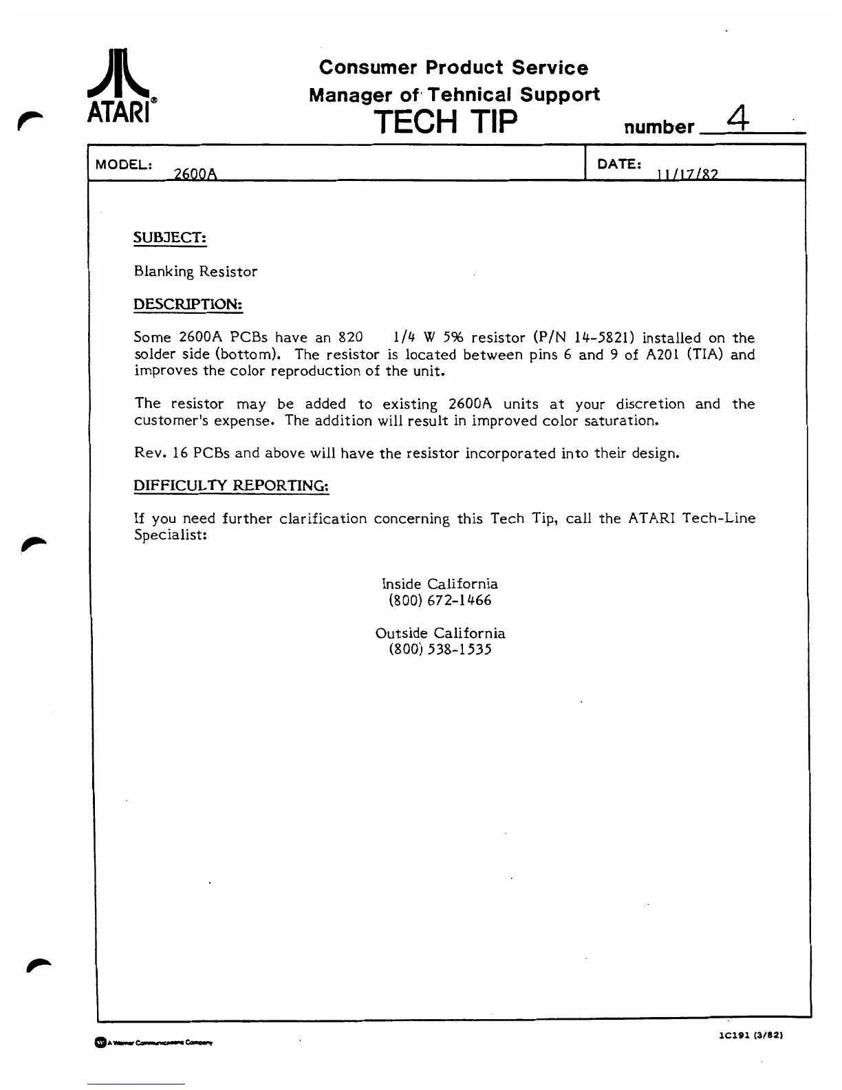
Blanking Resistor
Some
2600A
PCBs have an
820
1/4
W
5%
resistor
(P/N
14-5821)
installed on the
solder side (bottom). The resistor is located between pins
6
and
9
of
A201
(TIA)
and
improves the color reproduction of the unit.
The resistor may be added to existing
2600A
units
at
your discretion and the
customer's expense. The addition will result in improved color saturation.
Rev.
16
PCBs and above will have the resistor incorporated into their design.
DIFFICULTY
REPORTING:
If
you need further clarification concerning this Tech Tip,
call
the
ATARI
Tech-Line
Specialist:
Inside California
(800) 672-1466
Outside California
(800)
538-1535