SECTION
7
GAME
CONTROLLERS
OVERVIEW
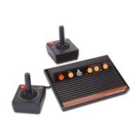
The following pages contain descriptions, schematics, and test procedures for the four
game controllers used with the Video Computer System.
JOYSTICK
(X-Y)
CONTROLLER
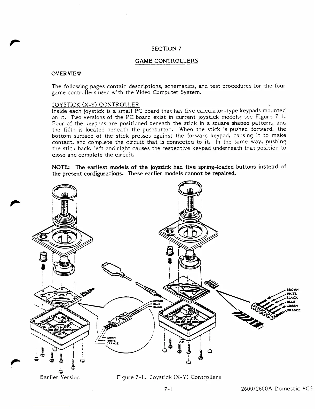
Inside each joystick is a small
PC
board that has five calculator-type keypads mounted
on it.
Two
;&ions of
the
PC board exist in current joystick models; see Figure
7-1.
Four of the keypads are positioned beneath the stick in a square shaped pattern,
and
the fifth is located beneath the pushbutton.
When the stick is pushed forward, the
bottom surface of the stick presses against the forward keypad, causinq it to make
contact, and complete the circuit that is connected to it. In the same way, pushing
the stick back,
left and right causes
the
respective keypad underneath that position to
close
and
complete the circuit.
NOTE:
The
earliest
models
of
the
joystick
had
five
spring-loaded
buttons
instead
of
the
present
configurations.
These
earlier
models
cannot
be
repaired.
Earlier Version
Fi~ure
7-1.
Joystick
(X-Y)
Controllers
2600/2600A
Domestic
VCS