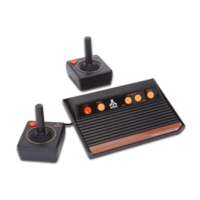
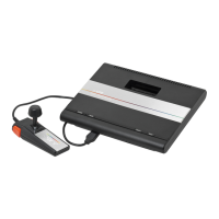
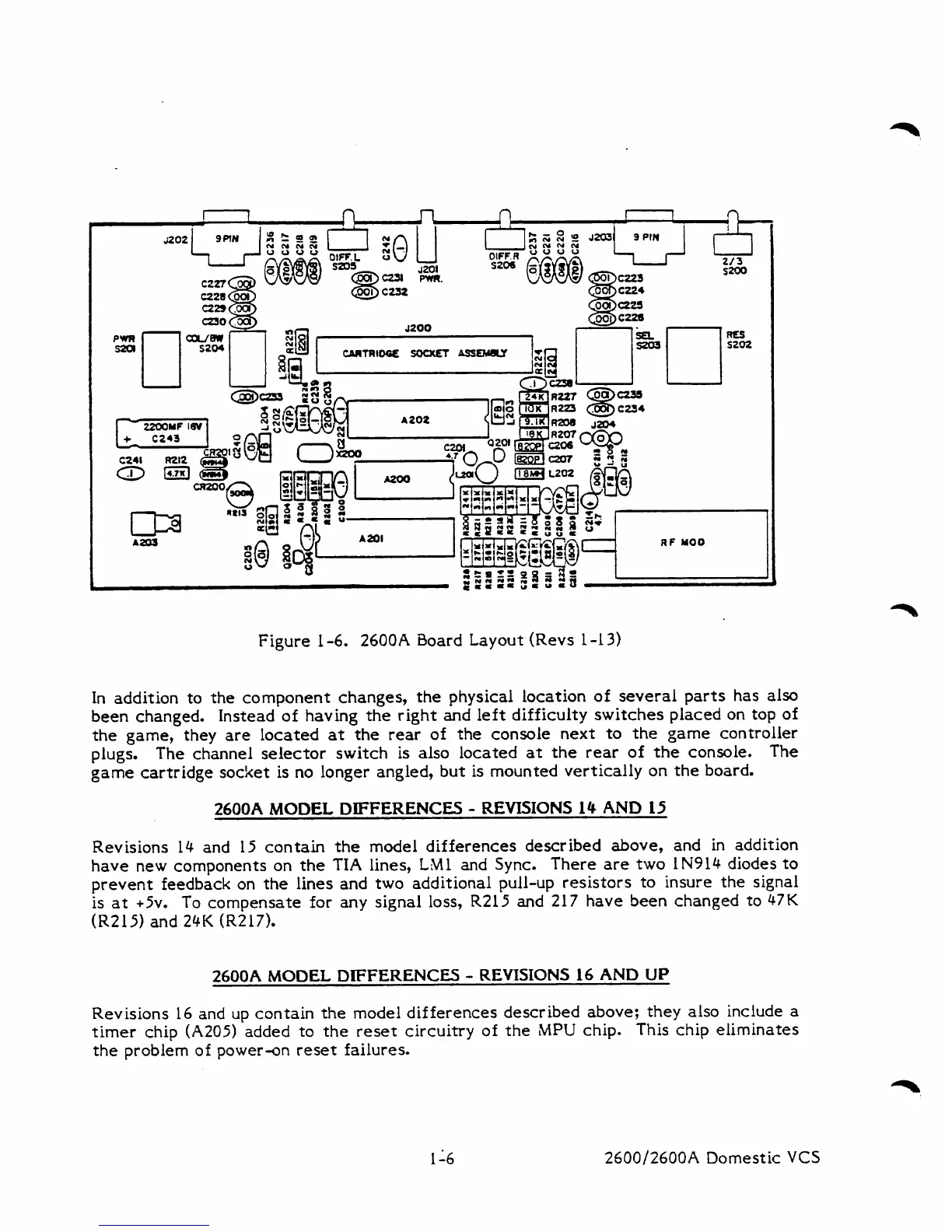
Figure 1-6. 2600A Board Layout (Revs 1-13)
In
addition to the component changes, the physical location
of
several parts has also
been changed. Instead of having the right and left difficulty switches placed on top of
the game, they are located
at
the rear of the console next to the game controller
plugs.
The channel selector switch is also located
at
the rear of the console.
The
game
cartridge socket is no longer angled, but is mounted vertically on the board.
2600A
MODEL
DIFFERENCES
-
REVISIONS
14
AND
15
Revisions 14 and 15 contain the model differences described above, and in addition
have new components on the TIA lines, LM1 and
Sync.
There are two IN914 diodes to
prevent feedback on the lines and two additional pull-up resistors to insure the signal
is at
+5v.
To
compensate for any signal loss, R215 and 217 have been changed to 47K
(R215) and
24K
(R217).
2600A
MODEL
DIFFERENCES
-
REVISIONS
14
AND
UP
Revisions 16 and up contain
the
model differences described above; they also include
a
timer
chip
(A205)
added to the reset circuitry of the
MPU
chip. This chip eliminates
the problem of power-on reset failures.
2600/2600A Domestic
VCS