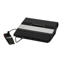
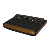
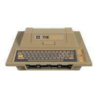
2600A
MODEL
MODIFICATIONS
Each
2600A
(Revs
1-1
3) model must have static strips placed on the front
panel switches (See Figure 3-51.
a
Check
each
connector and plug for
a
tiqht, secure fit. Intermittent
failures frequently result from a loose connector or plug.
a
Check that all cornponenets
are
properly soldered, and check for broken or
shorted
trace
lines.
e
If a unit exhibits
RF
interference that does not clean up using normal
adjustment methods, or if a series of lines and bright qr id distortions on the
screen
are
accompanied by a loud hum even when properly adjusted,
a
defective or leaking capacitor may
be
at fault. Replace C24l (.I
microfarad) and/or C242
(-1
microfarad) located respectively between the
power jack and voltage requlator.
ing
.
Figure 3-5.
2600A
(Revs.
1-13] Static Slodifications
3-6
2600/2600A
Domestic
VCS
 Loading...


