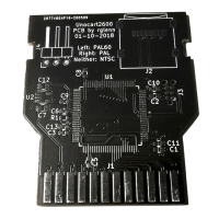
The Signal Tracing Cartridge
(STC)
is used to locate easily open or shorted traces in
the address and data lines of the 2600/2600A. The STC causes the 6507
microprocessor
(AZOO) to cycle through the entire memory space while executing "no
operation" instructions.
This is valuable because it puts a known signal on each
address and data line. Then the signal can
be
traced through to the JZOO connector,
the TIA and RAM-I/O chips.
Since the STC procedure is not easily reduced to a flowchart, it is presented
as
a
series of written instructions and illustrations on the following pages.
CAUTION:
The
STC
procedure requires three
known-good
chips
and
a
working
clock
circuit.
The
STC
should
only
be
used
after
all
other procedures
have
been
tried.
GETTING STARTED
Insert the STC into the 2600/2600A.
Turn on the unit. The television screen should be
gray or black. If it is "snowy" it indicates that you should return to the start of the
Diasnostic Flowchart. Set the scope sweep to
.5
microsec/division and set the vertical
to
1
volt/division.
ADDRESS LINES
AB@-
AB12
Check the address lines at-the microprocessor (H200). Check address lines, startins
wirh pin
5.
A
signal with a waveform similar to those shown in Figure 4-1 1 should be
seen on the address lines, with each succeeding address line's waveform having
a
frequency half that of the line before
it.
For example, A1 should be half the
frequency of
.A@.
If one or more of the address lines shows no signal, it is likely that
the line is either open or shorted to ground or +5v.
Check all traces and pins for
shorts.
If you have a defective address line and it is not open or shorted,
swapout the A200,
A202 and
A201,
in that order.
If all address lines have signals, trace those signals to the
JZOO
and the other chips.
Table 4-1 illustrates which address lines connect to which pins on 3200,
6532,
and the
A. The signal present on each address line of the microprocessor should also be
present on each pin of 3200,
6532,
and the
TIA
connected to that line.
If
the same
signal is not found, the trace line and/or solder joints between the microprocessor and
the dead pink) is (are) broken. Check the trace lines carefully to locate the break.
DATA LINES
DBO-7
Set the v~rtical on your scope to Zv/division. The data lines are tested very much like
the address lines. The only difference is that
the
waveform seen on the data lines is
different.
The signals you should see are illustrated in Figure 4-12.
If
any data lines
are completely inactive (simply remaining a constant voltage), it probably means that
the line is either open or shorted to ground
or
+5v.
Check the traces and pins for
P
shorts. If none are found, one of the three chips or the STC itself probably has an
internal short. Try swapping out the 6532, TIA, and the microprocessor. Also
carefully check J2OO for shorts between pins.
4-45 2600/2600A Domestic
VCS