If
all data lines have signals, trace those signals to JZOG and the other chips. Table 4-1
illustrates which lines connect to which pins of 3200,
6532
and
the
TIA.
The signal
present on each
data
line of the microprocessor should also be present on
each
pin
of
3200,
6532
and the TIA connected to that line.
If the same signal is not found, the
trace line and/or solder joints between the microprocessor and the dead pin(s) idare)
broken. Check the trace lines carefully to locate the break.
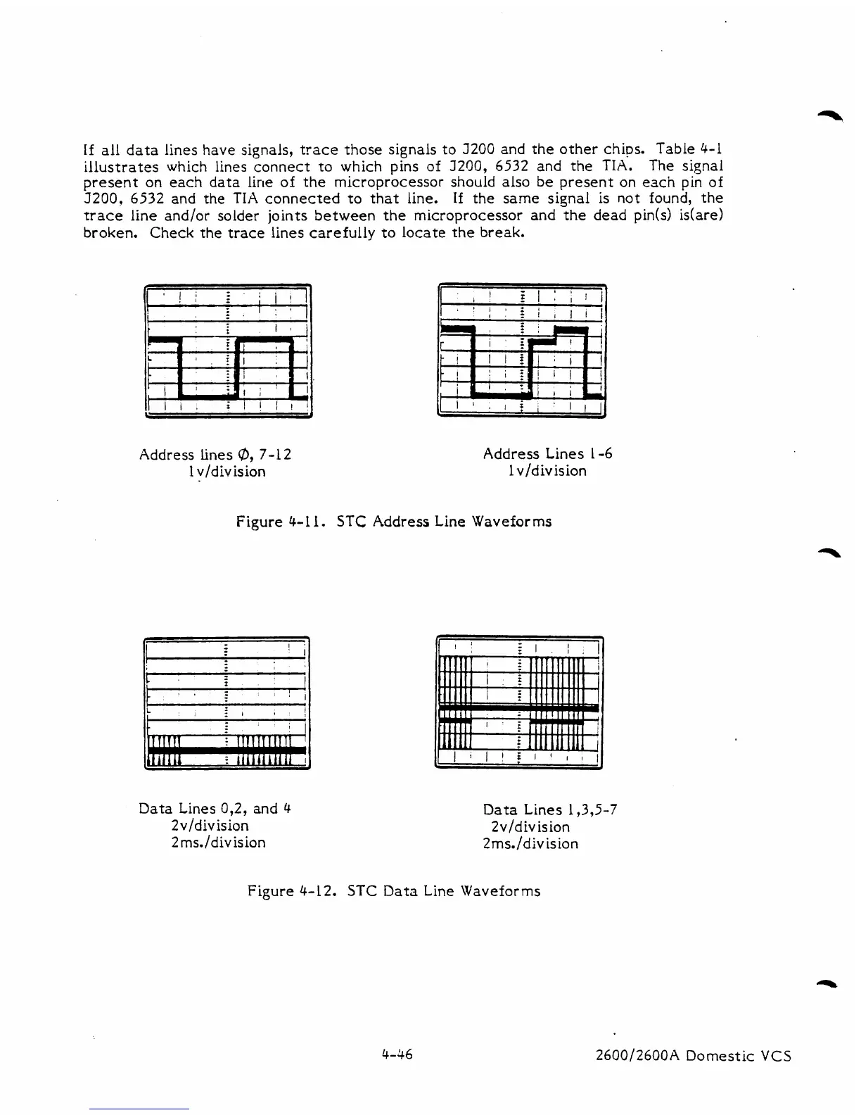
Address lines
@,
7-12
1
vldivision
Address
Lines
1-6
1
v/division
Figure
4-1
1.
STC
Address Line Waveforms
I
I
'
I
t
1
.
,
I!,
Data Lines 0,2, and
4
2v/division
2 ms./division
Data Lines 1,3,5-7
2v/division
2ms./division
Figure 4-12.
STC
Data
Line
Waveforms
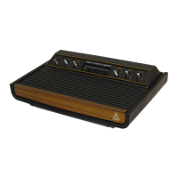
2600/2600A Domestic
VCS